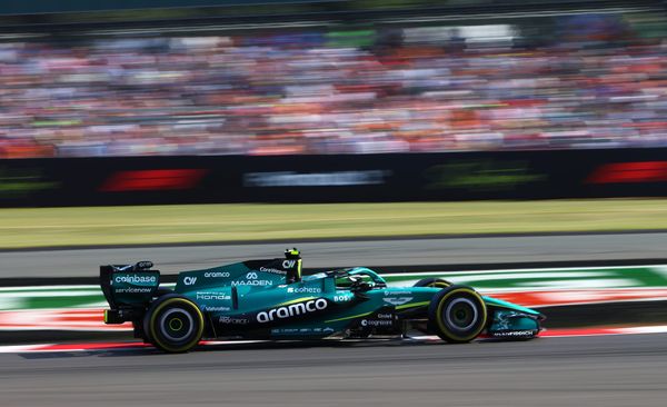
Gary Anderson: How F1 uses windtunnels, and how it’ll change
During the coronavirus-enforced delay in Formula 1, we’ve had no racing and therefore lots of people sitting around twiddling their thumbs.
So to keep everyone busy and justify their positions, we have probably the most widespread changes to the technical and sporting regulations that I’ve seen in almost 50 years of being involved in F1.
The $145million budget cap is a good start, but I still believe it should have been higher and perhaps set at $200m but with all costs included. At the moment, it leaves too much out and still doesn’t control overall spending for those that have access to the cash. The problem is $145m is still a dream budget for those who don’t have the resources, and we need to remember that status applies to half of the grid or more.
The current emphasis is on trying to create a more level playing field and the powers that be seem to believe that this can be done by controlling the amount of windtunnel and CFD runs each team can do. This is based not only on restricting the maximum level allowed for the successful teams but also allowing some more than the maximum for the not so successful. Confused? Well it only gets worse from here on in.

For 2021, the Sporting Regulations are made up of 82 A4 pages, nine of which are the Aerodynamic Testing Restrictions (ATR). This covers what will now be allocated to each team on a sliding scale depending on your constructors’ championship position.
As I have said before in previous articles, this is fundamentally wrong. It punishes you for success but not for domination yet it’s the domination of the few that has always affected the racing negatively. You just have to look at the TV coverage to confirm this. The director will always cut to a midfield battle if there is one – and usually there is – as opposed to following the leader driving around lap after lap with no other cars in sight.
Fewer windtunnel and CFD runs and less running time will affect a team’s ability to optimise a component before it goes into production. To ensure anything has a good chance of working when you get to the track, you try to create as much data as possible with the model to replicate as many real-life situations as possible.
These are the parameters that the aero restrictions allow you go through during an individual tunnel run:
The only permitted degrees of freedom of the model and Aerodynamic Testing Geometry during a run of Restricted Wind Tunnel Testing are:
i. Wheel rotation about the wheel axis
ii. Changes of ride height and roll angle relative to the ground plane and associated articulation of the elements representing the RATG suspension
iii. Changes of load applied to wheels through the elements representing the RATG suspension
iv. Steering of the front wheels
v. Changes of yaw angle relative to the incident air flow
vi. Simulation of differing exhaust flow
vii. Adjustment of the flap angle of the front wing
viii. Adjustment of the incidence of the rearmost and uppermost element of the top rear wing
ix. Adjustment or operation of sensors
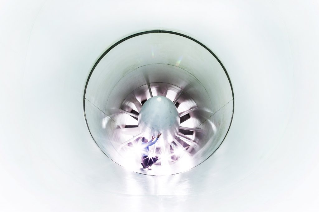
During a windtunnel run, the air and belt speed will be set and the model will go through a series of parameters to simulate the car going through a typical corner sequence. This new set of numbers will compared to a base test run.
The data generated by the tunnel from this run will be simply downforce, drag, yaw moment and side thrust. Temperature and humidity will also be added into the equation to ensure the data is comparable with other runs.
There will be thousands of data points taken during the run using a five-axis load cell in the model where the driver would normally sit. Also, most teams are now able to measure the load created directly from the suspension system and brake ducts, so they can separate the loads going directly into the tyre from the loads going through the suspension before it goes into the tyre.
On the model will also be hundreds, if not thousands, of surface pressure tappings. It’s not just about loads on the four wheels, if you are going to make progress you need to know exactly where those loads are being generated. Understanding this then allows you to make further improvements.
To maximise the data gathered from each run, most of these mode changes will be automated. The windtunnel operator might do it by hand, or it could be a pre-programmed sequence that simulates the car on the track.
Basically, you start the run with the car on the straight, close off the exhaust gasflow as if the driver has closed the throttle, close the DRS on the rear wing, change the ride height to simulate braking and turn the steering, which in turn will generate yaw and roll angle.
Then you re-instigate some of the exhaust gasflow and reduce the steering lock, which reduces the yaw and roll angle as you return to full exhaust gasflow to simulate the driver getting back to 100% throttle.

In real life, the aerodynamically-critical tyre profile is also changing. It’s difficult to simulate this in the windtunnel, but some teams will do their best at least to understand the potential effects.
All of this needs to be done to simulate various different-radius corners, with or without the DRS open on arrival.
We all know that teams strive to get good correlation between windtunnel data and track data. Reducing any of these tunnel data-gathering parameters will reduce the success rate of parts that are manufactured and taken to the track. There is nothing as expensive as making parts and them not working as planned.
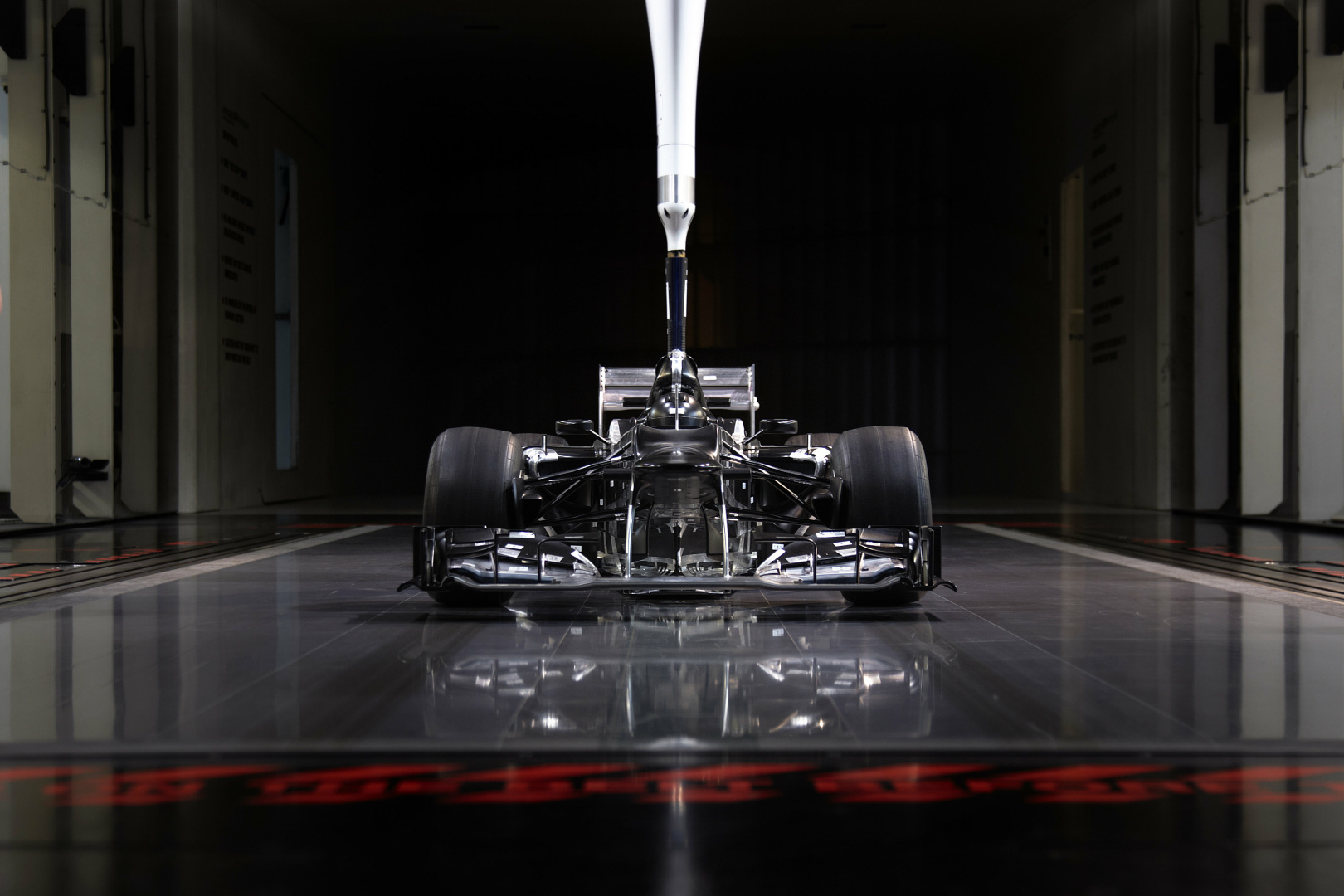
The actual windtunnel speed and model are also restricted to 50 metres per second (m/s) and 60% size respectively. The bigger the model and the faster the airflow, the more representative the data.
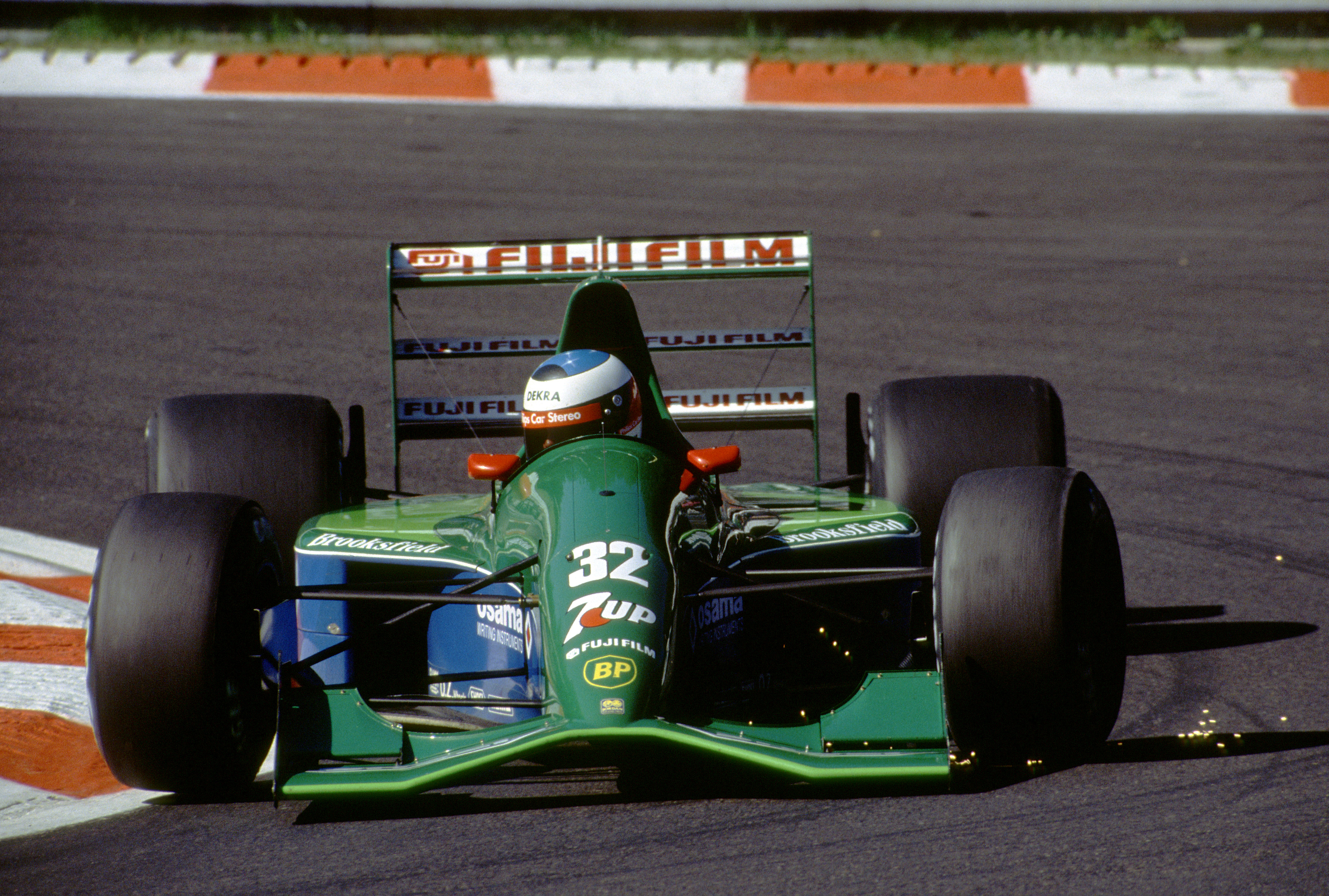
At Jordan, when we first went to Southampton for our one-weekend-a-month windtunnel programme to start the research and development of the Jordan 191, we used a 33.3% model. The loads on the components were so low that you could make parts out of breakfast cereal boxes. And we did!
Today, the loads are so much higher and all the components are either machined from solid or moulded from carbon, so basically as far as cost is concerned it’s more or less a 60% car.
Most of the windtunnel testing will be carried out by a tunnel technician. There will be a run plan and that will be defined to the minute and the objective will be to make sure that the data is complete and comprehensive. Very seldom will a technical director or aero head go to a tunnel test, but they will – as will a group of data analysis engineers – be able to review the data real time and try to spot any directions that might alter the intended run plan.
Changing the run plan is never an efficient way of going about things as nearly all the tests will lead in a direction to an end result, so if you alter it something else will go out of the window.
The big question is how does the FIA define what is a windtunnel run and how do you recognise this? This is done through the following part of the regulations, which I have added a comment to in bold:
a. The limits for RWTT will be the number of runs of RWTT, the amount of windtunnel occupancy time and windtunnel wind-on time.
i. During RWTT a single run will be deemed to commence each time the windtunnel air speed rises above 5m/s and will end the first time thereafter it falls below 5m/s.
ii. During RWTT, once the windtunnel air speed rises above 5m/s the RATG must remain fixed and unmodified until the windtunnel air speed returns below 1m/s.
(This is to stop some over-enthusiastic tunnel operator from going into the tunnel and making changes while the tunnel air speed was above 5m/s. Foolish but it has happened)
iii. Between runs of RWTT detail changes to the RATG and model are permitted.
b. Wind on time is defined as the amount of time in hours summed over the ATP, where the windtunnel air speed exceeds 15m/s for RWTT.
c. During RWTT, the first shift of occupancy will be deemed to commence the first time the windtunnel air speed is above 5m/s on a given calendar day, and will end at a time, declared by the competitor, when the windtunnel air speed falls below 5m/s on the same calendar day. A second shift of occupancy will be deemed to commence the first time the windtunnel air speed is above 5m/s following the end of the first shift of occupancy (on the same calendar day) and will end, either when the windtunnel air speed falls below 5m/s for the last time on the same calendar day or, at the end of the calendar day in the event a run is still in progress. Only two shifts of occupancy may be carried out in any one calendar day.
d. In the event of a demonstrated windtunnel failure or other force majeure the FIA will consider, at its absolute discretion, permitting additional occupancy to be used to compensate for that which is lost as a result.
e. For the avoidance of doubt any RWTT performed for the competitor by any associate of the competitor and/or by any contracted party of the competitor or of any associate of the competitor or any external entity working on behalf of the competitor or for its own purposes and subsequently providing the results of its work to the competitor during an ATP will be subject to these same limits as if the tests were performed by the competitor.
Restricted CFD falls under very similar controls. Basically, as with the windtunnel the amount of runs, computing power and model geometry are controlled. This means that going through thousands of iterations will not be possible.
This will lead to a reduced understanding of the car’s off-surface airflow, which has been something that has brought big returns over the last few years.
The off-surface air flow structure can and will influence the on-surface airflow and, in turn, the pressures on those surfaces, which are what improves the car’s aerodynamic performance.
For years we did this with a wool tuft on a wand, poking it through holes in the side of the tunnel and moving it to find vortices and what was producing them. From that, you could do things to strengthen those vortices or to break them up if they were detrimental.
A good example of this is the understanding of how the outwash front wing endplates affected the off-body airflow. That led to optimising the on-body airflow to improve its performance.
So how is this all controlled by the FIA? Well, there are lots of controls in place, but this rule is probably the catch-all:
Digital windtunnel image files in colour and with sufficient unobstructed field of view of the windtunnel working section to include the entire model must be recorded, referenced to other data collected and a copy saved including a unique time stamp to at least one second accuracy for the start of each individual run.
Should the FIA wish to access the images for inspection at any time they must be of adequate quality such that it is possible to use them to verify, for example, whether the front wing group (for 2021 described in Article 3.3 of the F1 Technical Regulations and for 2022 and beyond described in Article 3.9 of the F1 Technical Regulations) and rear wing group (for 2021 described in Article 3.6.3 of the F1 Technical Regulations and for 2022 and beyond described in Article 3.10 of the F1 Technical Regulations) are fitted.
In the case of other runs deemed to be non-RWTT in the context of this Article, for example using a RATG greater than 12 months old, or using the approved wing covers, the images must also provide a clear visual reference to assist in verifying this aspect of the test.
(The above has all been in place for a few years, but from 2021 we are going to have a new sliding scale.)
The limits for Restricted Wind Tunnel Time and Restricted Computational Fluid Dynamics are as set out in the tables below where:
P is the Competitor’s final position in the Constructors’ Championship of the previous year for the period 1 January to 30 June, or the position in the current championship.
Windtunnel limits for C=100%:
RWTT Runs 320
RWTT Wind On Time 80 hours
RWTT Occupancy 400 hours
CFD limits for C=100%:
3D new RATGs used for solve or # 2000 solve part of all RCFDs
Compute used for solve part or MAUh 6 parts of all RCFDs
Constructors’ Championship at the end of the day of 30 June, for the period 1 July to 31 December.
C is the coefficient (expressed in percentage form) by which the various parameters need to be multiplied in order to obtain the individual RWTT and RCFD limits for each Competitor. For RWTT Runs and RATGs the result of the multiplication will be rounded up to the nearest integer.
Coefficient C as a function of Championship position;
Value of C for 2021 in championship order 1st to 10th;
90%, 92.5%, 95%, 97.5%, 100%, 102.5%, 105%, 107.5%, 110%, 112.5%.
Value of C for 2022-2025 in championship order 1st to 10th;
70%, 75%, 80%, 85%, 90%, 95%, 100%, 105%, 110%, 115%.
(And if you have not been good with your housekeeping, then below is the price you have to pay)
Failure to comply with the limits of the ATR by a competitor will result in a reduction of the limits that will apply to subsequent ATP or ATPs for that competitor at the FIA’s absolute discretion but by a minimum reduction equivalent to 10 multiples of the amount by which the relevant limit or limits were exceeded without prejudice to further appropriate action. (For example, if a competitor carries out 325 restricted windtunnel runs against a maximum of 320 in an ATP, that competitor shall only be permitted to make 270 restricted windtunnel runs during the next ATP).
Most teams will carry out experimental concepts in CFD and then try to filter this down to model components. CFD is still further away from real life correlation than tunnel testing, so it’s good to understand airflow and the off-surface influence of on-surface airflow, but actual components for manufacture will still be signed off from tunnel testing.
CFD is useful for the design of a closed duct like radiator ducts and the underbody detail, which is very important for cooling efficiency. Also, the internal flow of the brake ducts.
The data from the tunnel and CFD will be produced as a huge set of numbers. A set of spreadsheets will be populated by this data and from that a set of graphs will be generated that will allow your analysis team, including the technical director and head of aero, to identify changes. From that analysis, the next stage of developments will be defined.
Every team will use their windtunnel and CFD time and runs differently. Some will be more efficient than others and I’m afraid that is one of the things that separates the top teams from the others. It’s this efficiency that is driven right through the company that makes one group better than another group.

It would be very interesting to see the last year’s actual tunnel and CFD percentage usage just to gauge how near the limit each team was. If we knew that, we could asses who would be able to make the most of their extra time and also who will lose most from their reductions.
How efficient you can be in terms of how many runs you do to test the same thing is all down to the confidence you have in how accurate your tunnel results have been in the past. If that is good you will minimise repeat runs. If it is not then you will spend valuable time doing repeat runs.
It’s not only the tunnel that can give spurious results, it’s also the quality of the model and its construction. It takes very little to throw off a set of results, so model changes and the time to carry them out correctly is critical to tunnel result efficiency.
Each team will know where they stand as far as that is concerned, but the objective for them all will be to reduce the percentage of human error.
So the big question is, will this make a change to the running order? For year one, the 2.5% step will be more or less invisible, but for year two when it doubles to 5% it will have some influence.
The only problem is that year two is a long way away and I’m pretty sure we will see more changes before that season comes around.
What I don’t like is that a team could pay a future development price for a mere flash in the pan result. That’s why I’ve argued it needs to be done using points and manpower. That way, it would recognise domination and then and only then would it bring some degree of equivalence.