Up Next

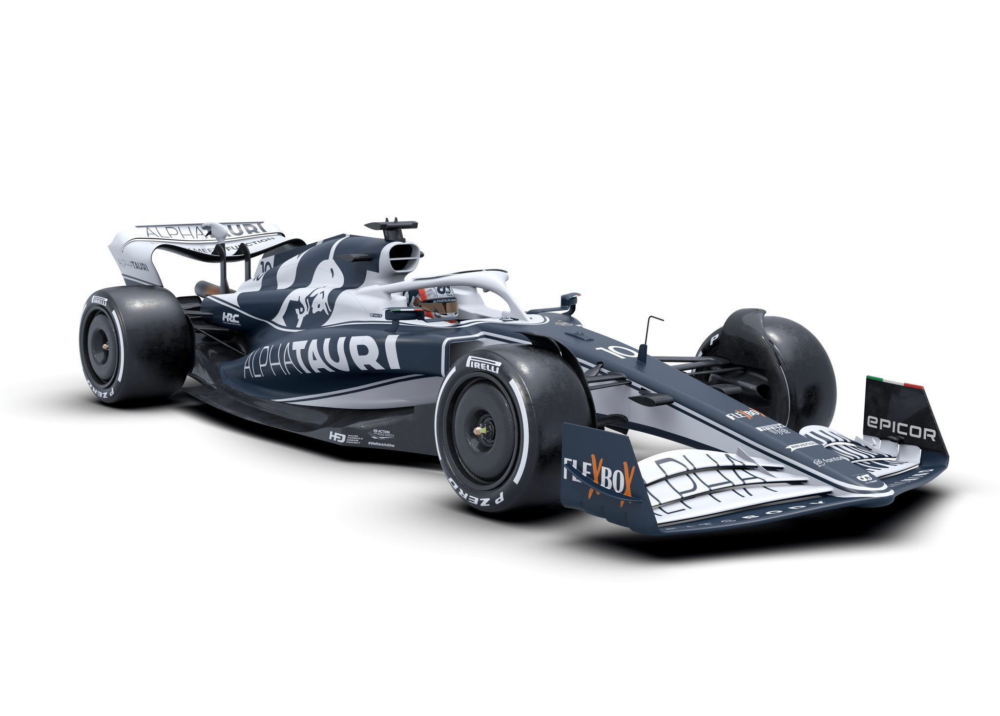
Because of the regulations, we all knew that the Formula 1 cars for 2022 would be fairly prescriptive and that the detail, more than the concept, would be the dividing factor between success and not being quite so successful. The AlphaTauri AT03 is further proof of that.
This is a really clean-lined and functional car. I have always said that a dolphin goes through the water with ease and generates very little turbulence and initially that is what I see in the AlphaTauri.
It is a bit of a cross between the Aston Martin and the McLaren, so there are some subtle differences but no major ‘wow’ factors, which is no bad thing. After all, it’s very easy to have a ‘wow’ part turn into a nightmare that doesn’t achieve the objectives.
With the caveat that we will no doubt see changes to the car for testing and there are potentially some details hidden, let’s take a closer look at the car.
Nose/front wing
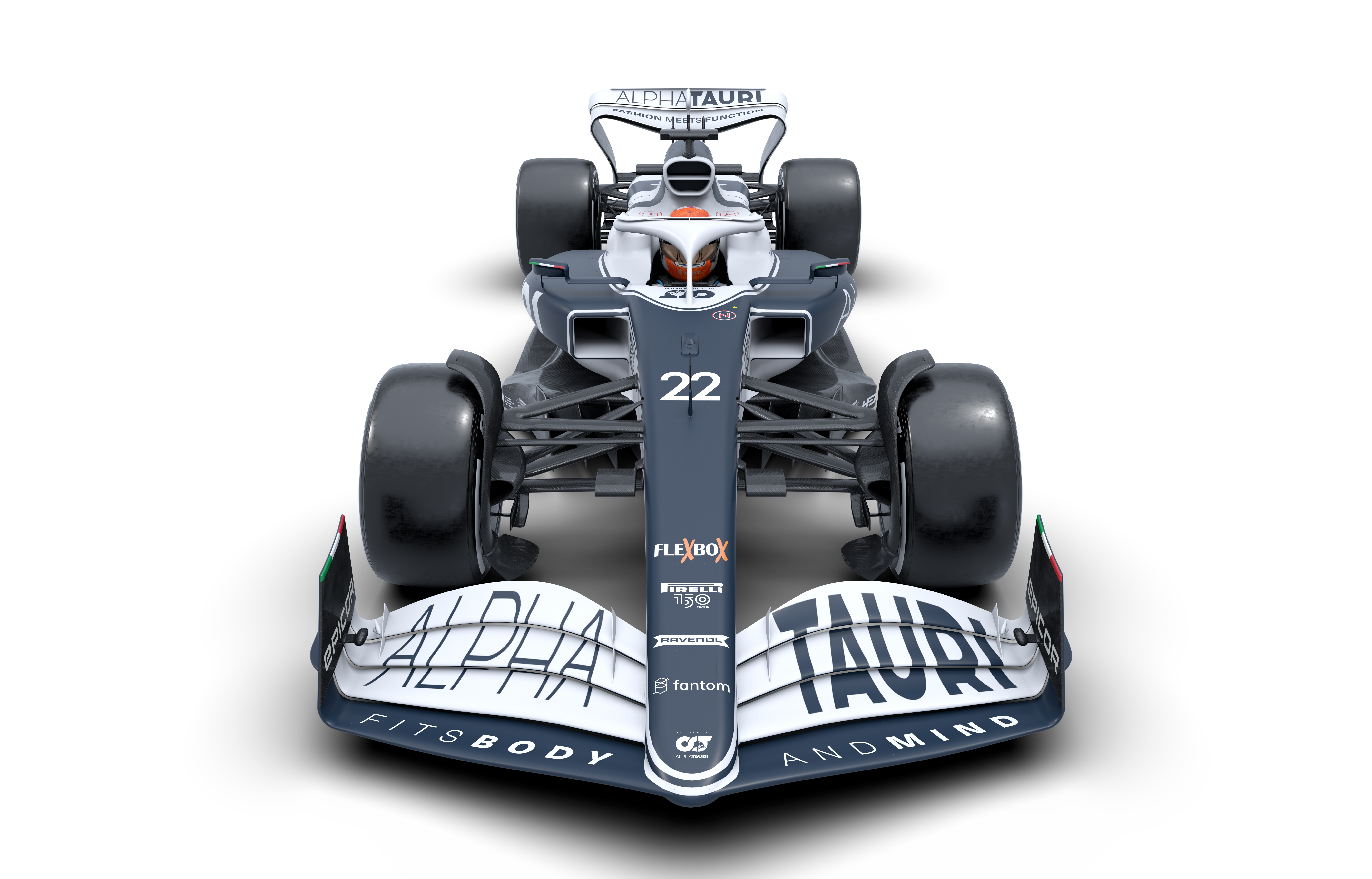
As defined by the regulations, this is a simple four-element front wing. There’s not much difference in the chord length of the elements.
The leading element is more of a mainplane than on the Aston Martin or McLaren, so the wing’s peak load centre should be that little bit further forward.
The flap adjustment will be the area between the two vertical vanes on the top of the wing.
These can also be used to generate a vortex, the inner one going around the outside of the outer sidepod vane, the outer one going around the outside of the front tyre.
Together with the subtle outward curve in the endplates, this will increase the outwash.
Nose and wing mounting
The undersurface of the leading element and probably the second element will run into the undersurface of the nose.
They are attached to the sides of the nose, which will generate a different flow field than the Aston or McLaren under the nose into the leading edge of the underfloor.
To compensate for that the inner ends of the flaps seem to have more angle on them, which will pull more airflow in underneath the chassis to the floor’s leading edge.
Front suspension
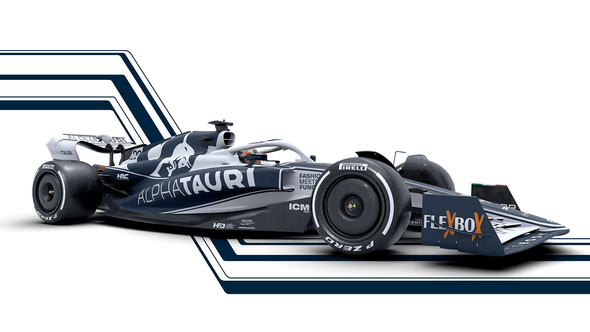
This is a pushrod-operated top-and-bottom wishbone design, so very similar to last year’s package.
The geometry looks to be more in line with what the tyre requests, with more camber as the suspension compresses at high speed to accommodate the higher cornering forces with speed.
It appears that the pushrod is driven by the outer end of the lower wishbone, so there will be no real load or ride height change with increased steering angle.
Front brake ducts
These are bigger than on the McLaren and probably more realistic in terms of what will be required.
The inner face of the duct runs into the mudguard to control the air spillage of the top inner corner of the tyre. It will be interesting to see if this reduces spray and improves visibility on a wet day.
Like other teams, AlphaTauri has shown its car has a low-down horizontal vane coming off the inner surface and a small vertical turning vane redirecting the airflow that is displaced when the tyre rotates onto the track surface into the low pressure area just behind the tyre.
Bargeboard replacement turning vanes
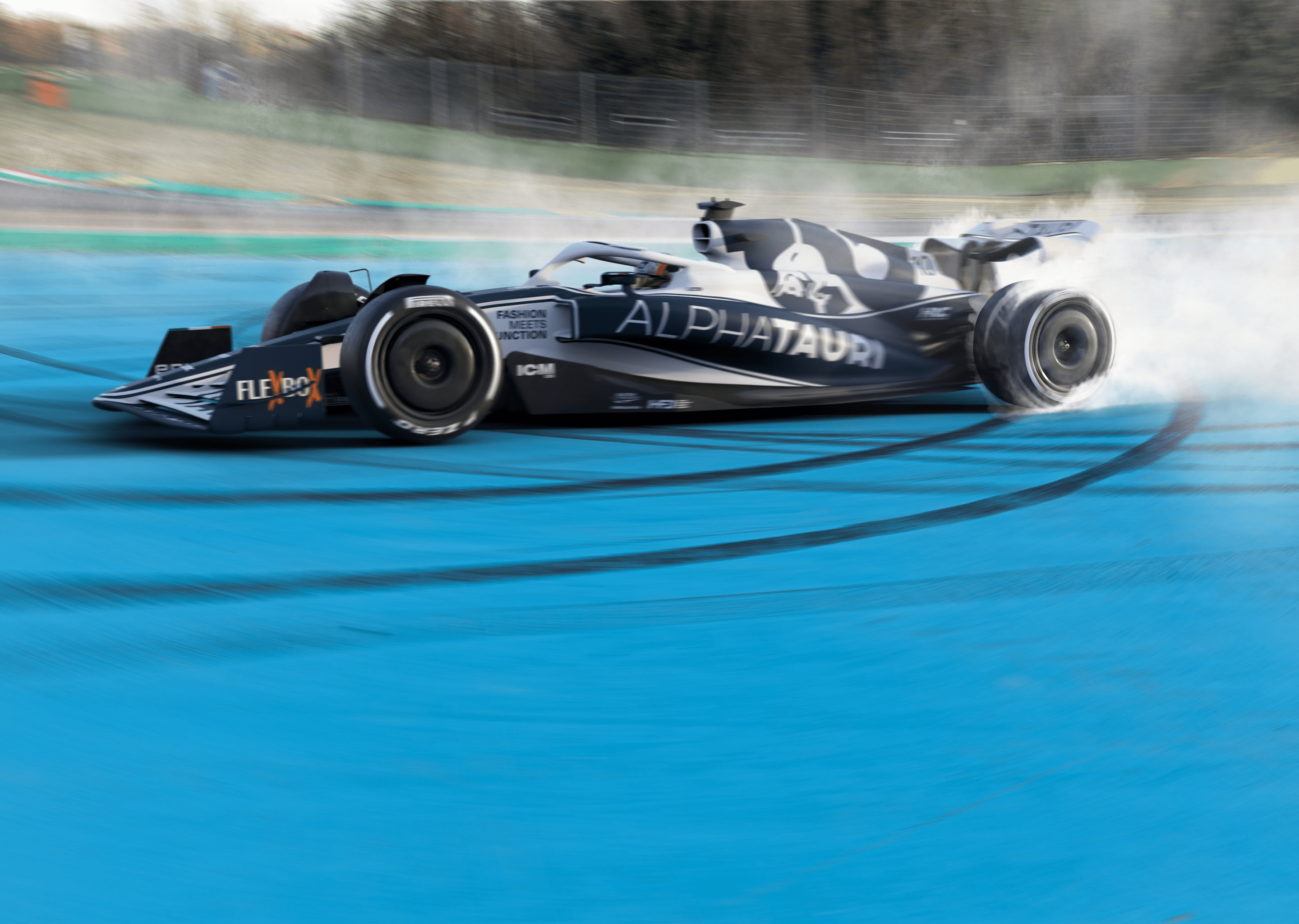
The outer barge board/splitter is similar to that of the Aston Martin in length. This is to separate the turbulent tyre wake from the airflow going into the underfloor.
There are two other vertical turning vanes coming down from the surface of the underfloor. These are going to be very powerful because they will separate sections of the underfloor and will turn some of the airflow outwards, meaning that the flow nearer the centre of the car is what the diffuser has to work with.
Underfloor leading edge
This has a small radius leading edge very similar to the McLaren. A small leading edge makes it more critical to flow direction and this is optimised as much as possible with the front wishbone forward legs both top and bottom.
You are permitted a small angle increase or decrease on these components and that will be set to suit the flow direction required for the leading edge of the floor.
Sidepod leading edge
Like Aston Martin, this is a very square inlet. The top is at the maximum height, while the vertical outer edge maximises the inlet size and keeps it as near the centreline of the car as possible to keep it away from the front tyre wake.
But this all starts because you want the lower edge to be as high as possible because it diverts the flow coming around from underneath the chassis into the aggressive undercut on the sidepod.
Sidepod profile
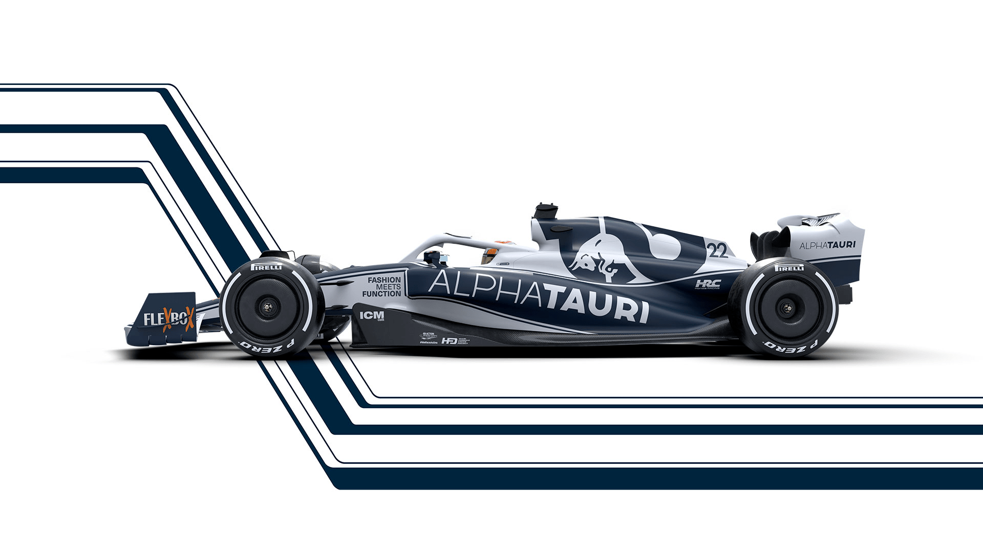
The sidepod profile in both plan and side view is aesthetically very pleasing. AlphaTauri’s is a mix of the two approaches we’ve seen so far.
There is an aggressive undercut from front to back to allow the airflow to get pulled through over the floor and diffuser surface by the low pressure at the rear of the car. This helps the performance of both the front and rear downforce-producing devices and improves the entry direction to the underfloor.
The top surface of the sidepods also sweep downwards to help airflow over the sidepod and into the area of the diffuser, beam wing and lower surface of the upper wing.
The upper part, as it sweeps away from the chassis and past the engine, neatly turns into the radiator exist. There don’t appear to be any louvre exits on the body top surface, but these could be fitted as cooling adaptions when they require them.
All in all, it’s a very elegant and functional sidepod solution with lots of positives.
Air Intake
This is fairly conventional but with a horizontal splitter.
With the turbo mounted low on these cars, I would assume that the lower opening feeds it, allowing the upper opening to be used for cooling of whatever components or radiators are mounted on top of the engine.
Radiator exits
These are quite big and, as in the past, head out the back of the car.
They are sort of each side of the rear top wishbone, so in effect exiting into the flow that the beam wing is presented with.
The two-element beam wing is new for this year. It will act to improve the performance of the diffuser and thanks to being a fairly aggressive piece of kit can probably cope with the lazy airflow coming out of the radiator exits.
Coke bottle area
This is maximised by the radiator exits being placed high up and the dramatic undercut of the sidepods.
Getting as much flow through this area between the inner surface of the body and the inside of the rear tyre simply helps everything – more airflow over the diffuser, more airflow to the beam wing and more airflow to the underside of the rear wing.
Rear suspension
The rear suspension, along with the gearbox and hydraulics, comes from the mothership Red Bull. So assuming it is the same and what we can see is real, it is interesting, no, not that it is pullrod operated.
However, it has a very high mounted lower wishbone and it looks like the driveshaft is higher than the centre of the rear wheel.
We – and especially me – have taken in by teams offering up less than true renders and this could be just that – especially as some of the lower suspension members are missing from the render, as it is a Red Bull package I’m intrigued to see what they end up with.
I could come up with all sorts of reasons and solutions for doing this, but I’ll reserve judgement for later when we see more of what we might call a running example.
Rear brake ducts
There’s not much of a brake duct visible. With the majority of the rear braking coming from the ERS (energy recovery system), they are not really required to cool the brakes and are used more as a turning vane for the airflow that is spilling around the inside of the rear tyre.
The combination of that and mounting the horizontal turning vanes between the outside of the diffuser and the inside of the rear tyre, makes this area very powerful in that these components help seal the sides of the diffuser and also apply their forces directly onto the upright assembly – hence directly into the tyre contact patch.
Rear wing
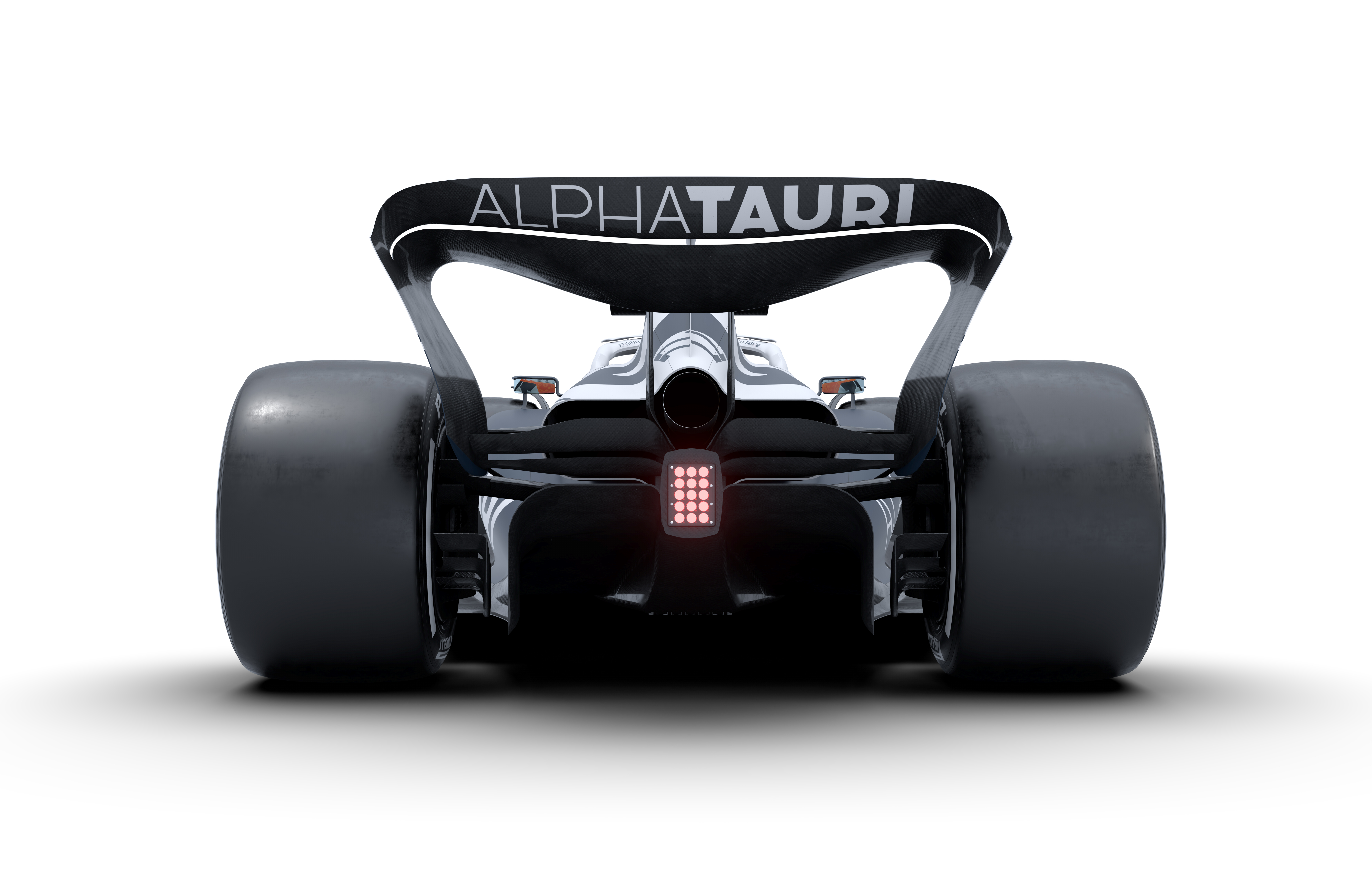
This is in line with the new regulations but is more profiled than the McLaren version.
It’s a twin-pillar design with the DRS actuator between the mounts. There is a small line at each end of the flap just after it curves downwards, which could be the flap split for when the DRS is activated. If so, it is further out than the other cars we have seen.
Beam wing
This is a two-element component with an increased chord length flap in the area above the diffuser.
The beam wing is one of the major additions for this year in an attempt to increase the height of the turbulent wake behind the cars, allowing a following car to be in cleaner air.
Diffuser
Higher but narrower than we have seen for many years, this, in conjunction with the beam wing, is all about producing a bigger percentage of the downforce from underneath the car whilst reducing the turbulence they generate. The trendy word for it is ground effect.
CONCLUSION
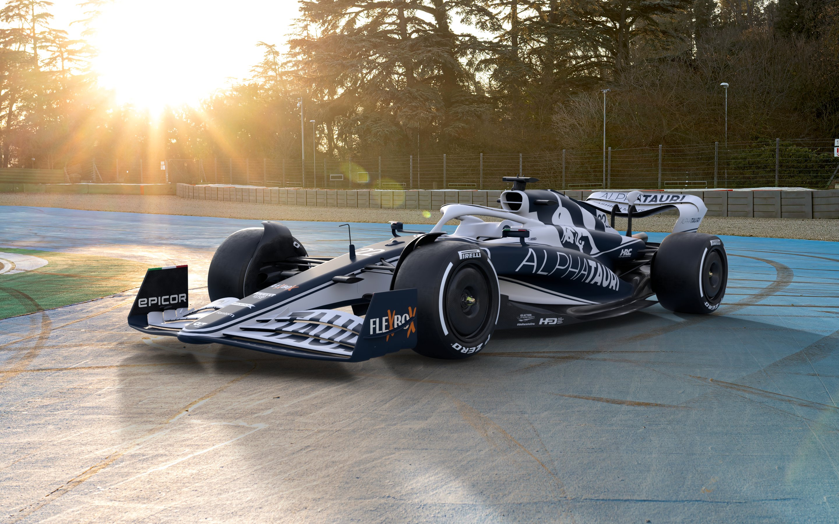
I’m actually very positive about what AlphaTauri has come up with. It is what we should expect from these prescriptive regulations in that it is a combination of the Aston Martin and the McLaren and, in my humble opinion, it has features that are the best of both designs.
It will be a whole new learning curve for the teams when these cars hit the track. If there is anything that they can’t really simulate, it is the effect on a moving device designed to produce aerodynamic forces when it is running near the track surface.
There is no substitute for track time to learn all about that, so perhaps a small team with a decent group of people that rely more on gut feel might just get a better understanding quicker than a big team that is solely driven by data.
We shall see what the real article looks like when it takes to the track and there could be some changes, but if what it has is an evolution of this it could be a good, tidy package.


