How F1 2022’s varied front wing designs work

We have seen some differing solutions from Formula 1 teams in how they have adapted their front wing philosophy to tackle the new aerodynamic regulations for 2022.
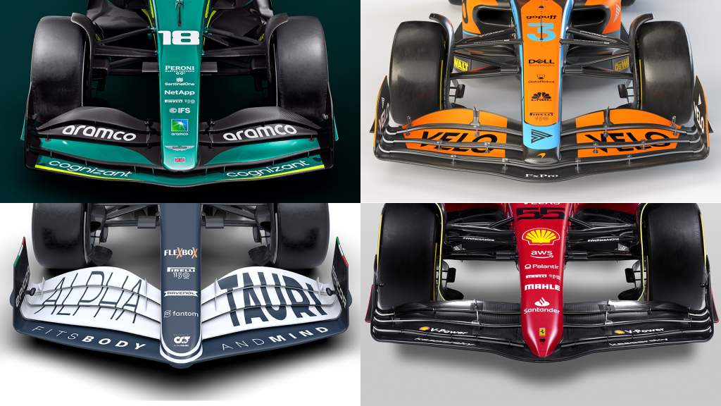
Some have raised sections on the wing centre, some have lower sections on the wing centre, some have a slot gap all the way across the wing and some block off this area with the nose to wing mounting.
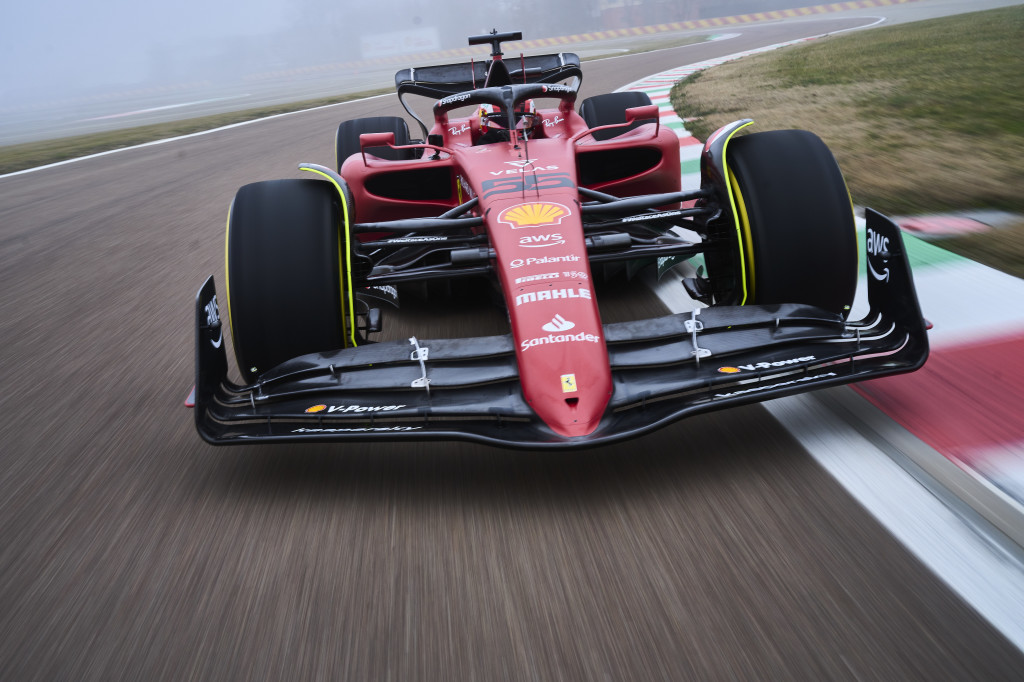
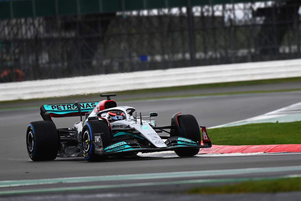
Aston Martin, McLaren and Alfa Romeo all have the first slot gap full-width, and the hints from Alpine’s renders and Haas’s shakedown suggest they’ve gone that way too. Mercedes, Ferrari, AlphaTauri have the nose fasten directly to the first element meaning that they don’t have a continuous slot gap.
It’s important to maximise the airflow that is attached to the underside of the nose. This airflow will then be pulled into the leading edge of the underfloor, so the more energy it has in it when it arrives there the better for producing downforce.
The airflow that comes into the leading edge of the floor is what the diffuser has to work with and the faster it is travelling the better.
The diffuser then pulls that airflow that arrives at the leading edge of the underfloor through the throat area (the lowest point of the floor) of the underfloor. As it does this, it increases in speed to enable it to fill the volume of the diffuser.
If you try to expand it too much, you will stall the diffuser and it will be inconsistent. If you don’t expand it as much as you can, you will lose some downforce but it will be more consistent. Managing where and when this all happens is one of the major reasons for the differences in the performance of the teams.
This is also why we talk so much about sealing off the sides of the floor and diffuser. The complete underfloor is at a lower pressure than the airflow around its perimeter, so because of this the diffuser will pull airflow in from anywhere it can.
This will fill the volume of the diffuser. In doing that, it will reduce the airspeed going through the throat of the underfloor, reducing the downforce it will produce.
Downforce is produced at the square of the speed. A simple example of that is that twice the speed equals four times the downforce. But it’s not about the car’s road speed, it’s really about the car speed relative to the airspeed. That means with a headwind you get more downforce and a tailwind you get less.
You can’t do anything about the wind direction, which is the same for everyone, but what you can do within your car design is minimise the blockage of the airflow. If the blockage along the car is greater than necessary, it is very easy for the car to actually start pushing the airflow along with it. This reduces the speed differential between the car and the air and reduces downforce – again, this detail is one of the main reasons we see a difference in performance between cars.

Every car does this to some extent, mainly because they use the same size of wheels and tyres. In simple terms, it is why a following car gets a tow from the leading car thanks to the hole created in the airflow. Yes, it’s turbulent airflow – although the idea of this year’s rules is it is less turbulence – but, like everything in life, you don’t get something for nothing.
The front wing is the first thing to see the airflow, so what you do with and how you work this component has an effect all the way down the car.
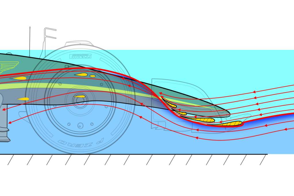
To showcase how the front wing is intended to work, we have created an illustration showing how the airflow is managed on the centreline in comparison to the airflow at the maximum flap height/angle further outboard. These are based on what we have seen so far of the Aston Martin AMR22.
For the technically-minded purists – yes, this will be affected dramatically by transverse airflow set up by the nose and front tyre blockage and any vortices that might be generated with gizmos such as the front-wing flap adjusters. But this is to illustrate the fundamentals.
Illustrations by Rosario Giuliana
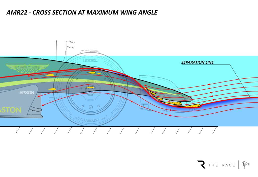
Our first illustration is a cross-section at the maximum wing angle. You can see how the airflow separates on the leading edge of the front of the first element and then flows up the under surface. A small amount of the airflow goes through each of the slot gaps.
If the wing were a simple single element, it would have to be run at a very shallow angle. As you put more camber (curvature) into it, the airflow will stall fairly early on the undersurface.

You then put a slot gap in that location, and because of the low pressure under the wing and the high pressure on the top surface you get high-speed flow through this slot gap. Then you put more camber into the profile from that first slot gap rearward and again it will stall somewhere in the undersurface, so you add another slot gap.
Depending on how many elements you are allowed to have, which for 2022 is four, you keep going altering the chord length of each element, adding camber to those elements and optimising the slot gap position, size and overhang until you get the best lift-over-drag package.
You also need to take into account that the front wing is running near the track surface. Because of ride height change with speed, the way the wing works will change through the speed range.
All of this refinement allows the wing angle to be set at a higher angle without suffering too many problems with separation on the lower surface. If you still have separation, it’s not too big a drama as long as you understand where it is happening on the wing span and when it will happen and how to deal with it so it doesn’t control your car’s performance. But having unknown characteristics is not a good place to end up with a wing design.
As the airflow comes off the top flap’s trailing edge, it is then realigned as effectively as possible using the track rod, upper and lower front wishbone legs. If this is done too early or too aggressively it can affect the performance of the front wing.
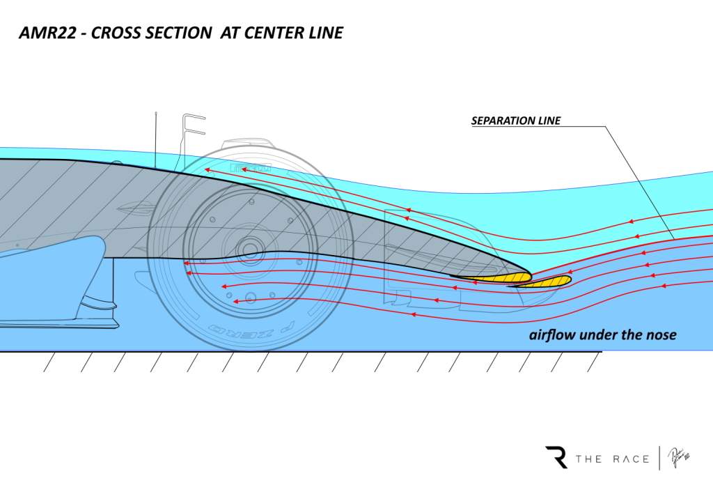
Our second illustration is a cross-section at the centreline of the car. The separation point is on the leading edge of the nose, which is actually the leading edge of the second wing element.
This allows airflow through the first slot gap, helping to keep it attached to the underside of the nose. This separation point is higher and further rearward. This central section of the first element has more of an upturned leading edge than it has further outboard so the separation line and the angle of attack of the airflow arriving there is quite different.
This is because in the area of the nose, you don’t have the other slot gaps to work on to keep the flow attachment on the undersurface of this first element or the underside of the nose. You only have one hit at it and by raising the leading edge you introduce more flow to that area.
Yes, you will probably lose a little bit of front wing downforce, but it will be more consistent. And consistency in this area is critical because if it stalls, it will affect the car dramatically further downstream,
Once this airflow gets past the centreline of the front tyres, which create a huge percentage of the car’s blockage, it will then get pulled outwards by the low pressure behind the front tyres.
The responsibility for managing the airflow from there on rearwards is passed on to the leading edge of the underfloor and sidepods, but that’s another story for another day.
All teams are attempting to achieve similar effects with the front wing, it’s just a question of where you make the compromises – and there are always compromises – and how it interacts with the rest of your car concept.