Up Next

Our eagle-eyed photographers have been at work again. These shots of a significant change on the 2024 Mercedes during pre-season testing show what Formula 1 development is all about, nothing stands still.
For day three, Mercedes has moved the upper wishbone rear leg inboard mounting downwards.
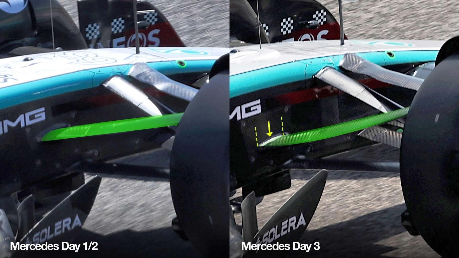
This movement will increase the anti-dive on the front suspension significantly. Normally in F1, we talk about dimensions in tenths of a millimetre, but as we can see this is about a three centimetre vertical movement.
The actual structural wishbone will be metal, probably titanium. It will be inside of a carbon aerodynamic shroud, so the mounting of it will be underneath this carbon cover panel, which is held on by four fixings. In effect, it is the end of the carbon wishbone shroud.
Doing it this way allows Mercedes to optimise the aerodynamic effect of the carbon shroud without the hassle of making new structural wishbone components.
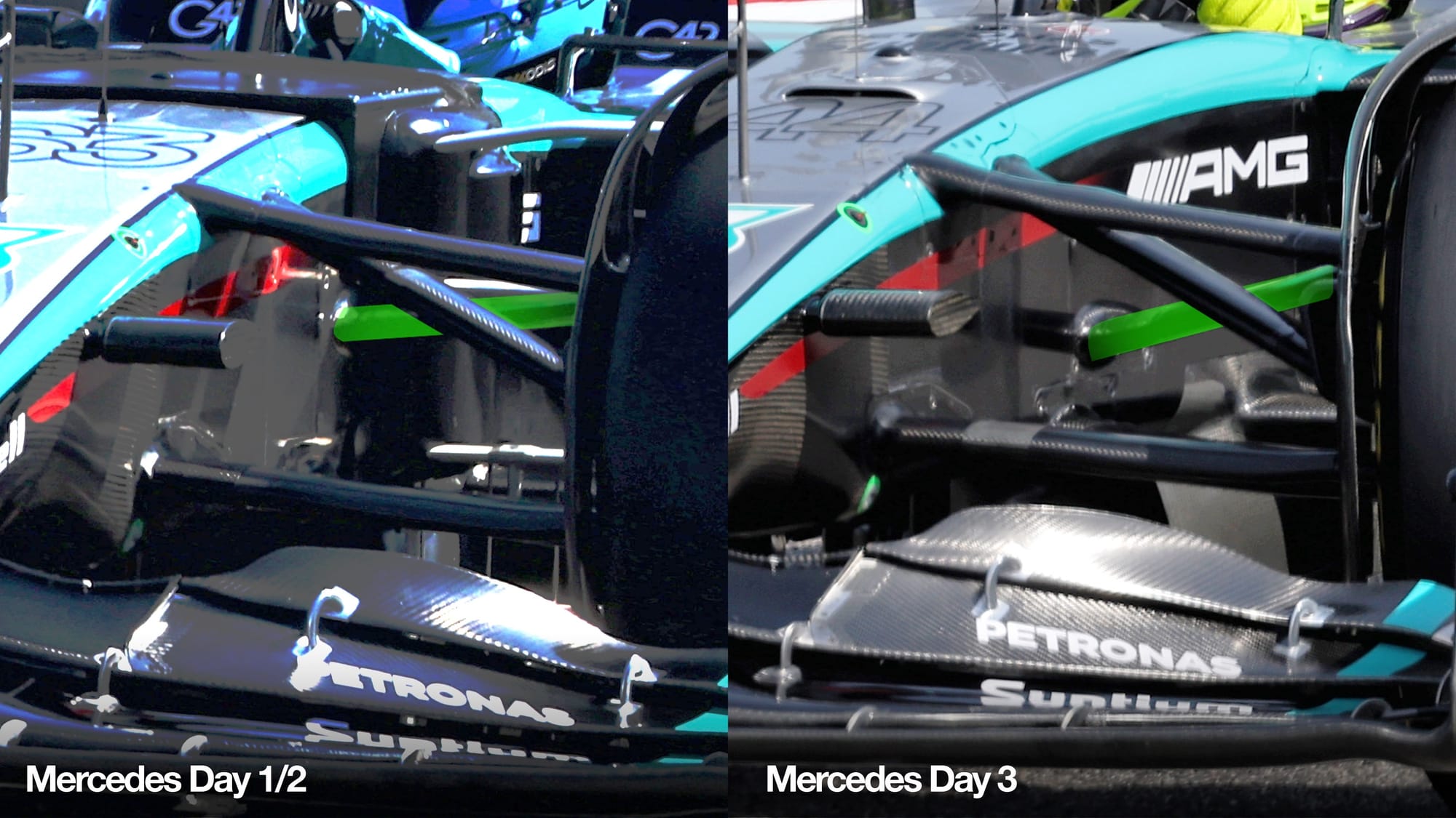
What the team's done allows it to experiment with how much anti-dive it can get away with. The more you have, the more you are likely to be suffering from locked wheels. The lower pick-up point is a lot of anti-dive so you might as well have a couple of options. So this is less likely to be Mercedes preparing a fallback option, and more it giving itself the flexibility to experiment with different levels to see how far it can go.
The braking load on these cars is initially in the region of 6g. That equates roughly to a 300kg weight transfer from the rear of the car onto the front of the car. That needs to be supported by more than just stiffer springs.
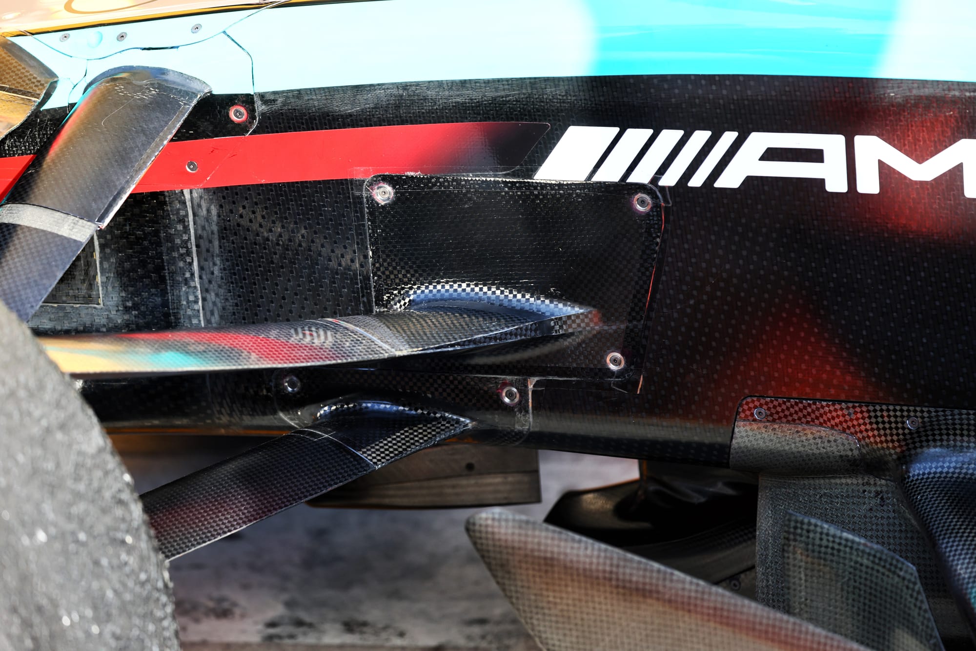
Supporting the front of the car under braking using anti-dive to resist this weight transfer stops the car crashing into the ground on initial braking. It also allows you to run softer springs, which helps normal handling requirements.
On the rear of the car, it’s the opposite. The teams use what is called anti-lift to keep the rear of the car down during that initial braking phase.
The control of the height of both ends of the car is critical to braking stability and, in turn, aerodynamic centre of pressure stability.
A REAR SUSPENSION CONCERN
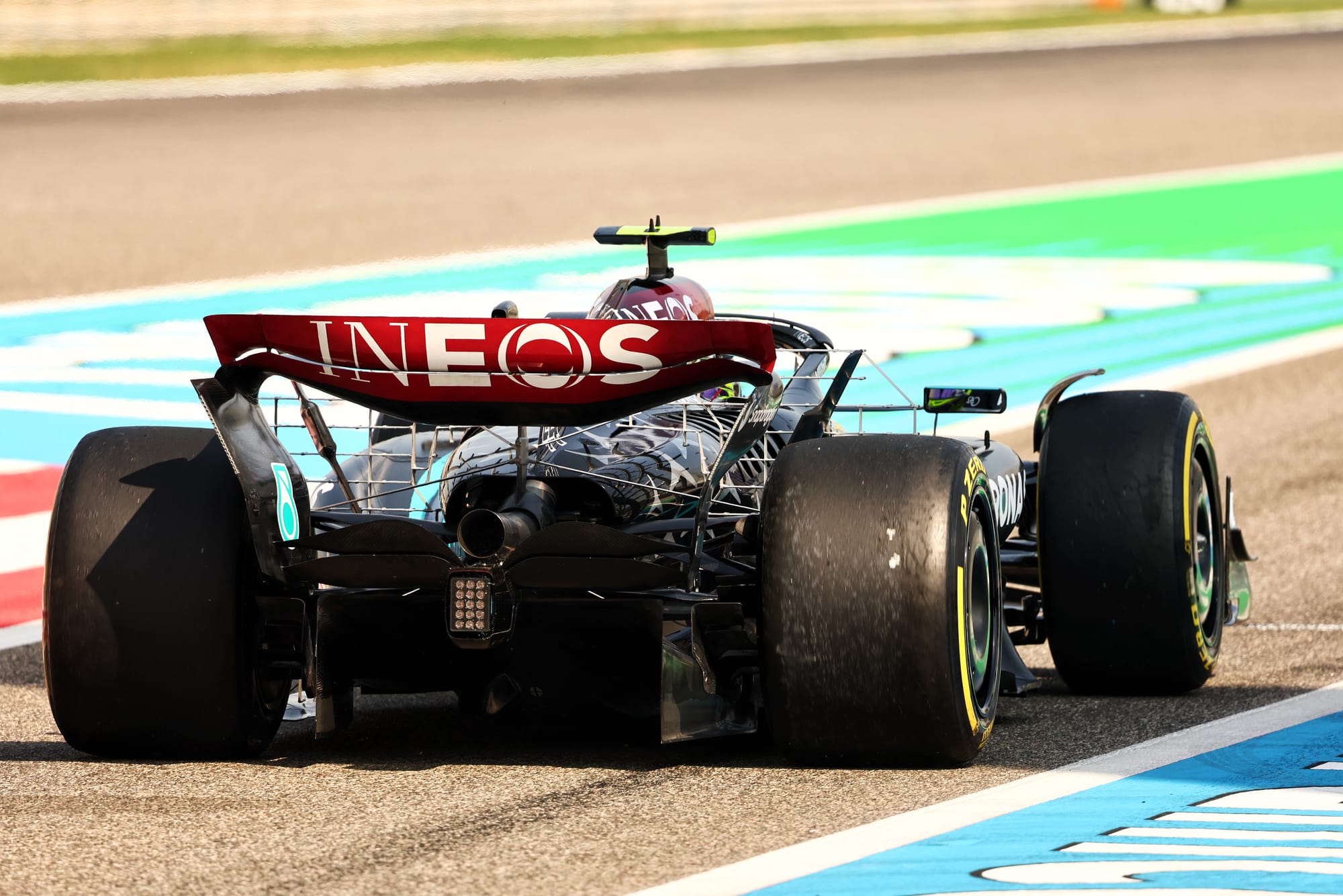
While the Bahrain track was being repaired for the second time during testing on Friday morning, I also took a quick look at the new Mercedes’ rear suspension.
Since I first saw it on the Aston Martin, which uses the same gearbox and rear suspension set-up, I was concerned about the shallow angle of the pushrod.
The shallower the angle, the worse the mechanical ratio and the higher the loads in the system become to overcome that mechanical ratio.
The wheel has a vertical movement, so if the pushrod was mounted on the outboard end of one of the lower wishbone legs then the other end of it, which attaches to the rocker, would have the same vertical movement. If it was mounted horizontal to the same leg, then the end mounted to the rocker would have no vertical movement.
Getting a decent mechanical ratio between the vertical movement of the wheel and movement of the other end of the pushrod is relative to the angle of the pushrod to the wishbone leg that the outer end is attached to.
In this picture I have highlighted the rear suspension members as follows:
Pushrod: red. Top wishbone rear leg: dark green. Top wishbone forward leg: light green. Lower wishbone rearward leg: dark blue. Lower wishbone forward leg: light blue. Driveshaft and its cover: orange. Top rocker: magenta ellipse. Torsion spring: yellow.
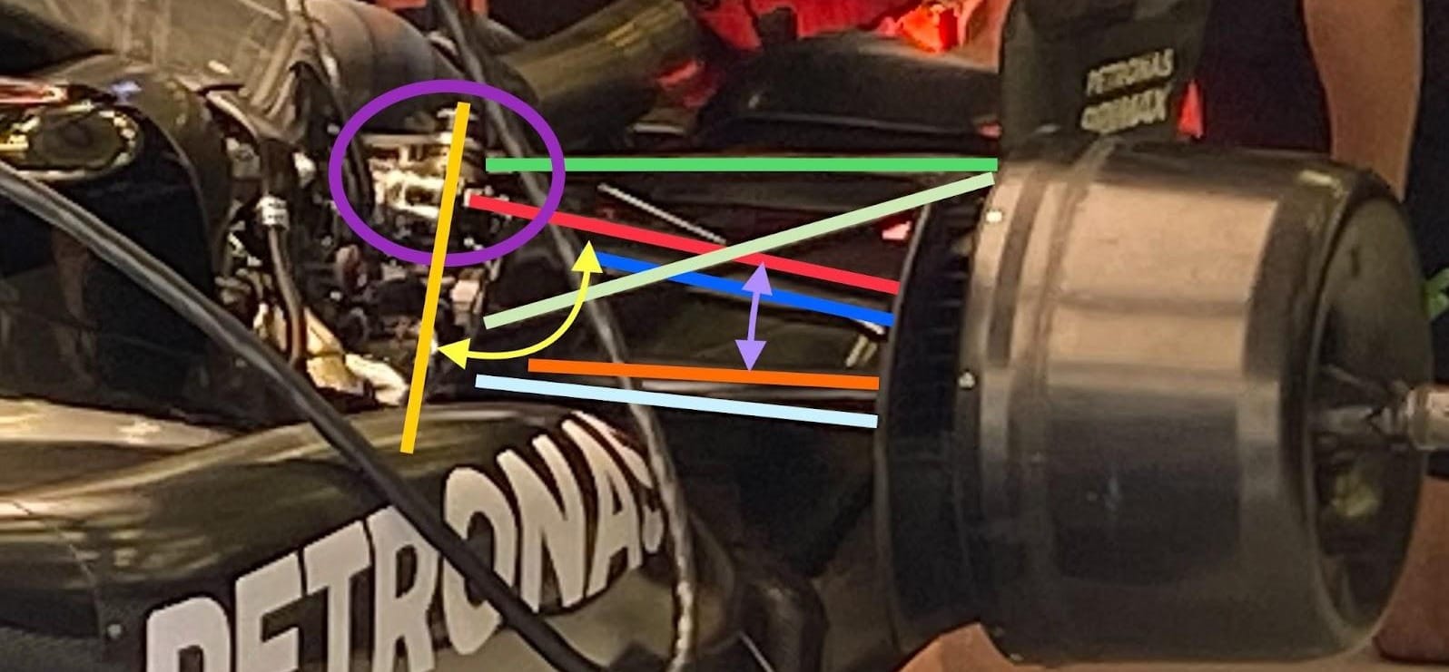
The angle of the pushrod that I am talking about is actually between the red line and the dark blue line (above). However the dark blue line inboard mounting is much further rearward than the inboard mounting of the pushrod, so in this picture basically it looks like there is no angle difference.
To show what I mean I have put a double headed arrow in light magenta between the driveshaft cover and the pushrod. The driveshaft is fairly horizontal in a true front or rear view, so it gives a reasonable indication of what the pushrod angle to wishbone leg would be, and as you can see it’s quite shallow.
As I said above, to get the mechanical ratio that you want means it has to all be done in the inboard rocker ratio. To achieve that, it’s millimetres of vertical wheel movement - which gives you millimetres of pushrod inboard end movement, which at this angle will be very little.
With the lower mounting of the torsion spring fixed it is then that pushrod movement relative to degrees of rocker rotation, which is what rotates the torsion spring generating the support for the car.
You would normally have the torsion spring and pushrod at roughly 90 degrees to each other, and as we can see from the yellow double headed arrow (below) they are not far away from that.

However, the angle of the torsion spring might just be compromised by the gear cluster in that area of the gearbox. I believe the Red Bull torsion spring to be further forward, possibly in front of the gear cluster.
As I have said many times, everything is a compromise. However, I’m not 100% sure Mercedes has made the best one here.


