Gary Anderson: The course corrections in Mercedes’ F1 2023 design
Last year, the big visual difference between the Red Bull, Ferrari and Mercedes was the sidepod concept. Ferrari has stuck with its concept, albeit with a few refinements, and we haven’t seen the Red Bull in detail yet, but the big question was always whether Mercedes would make a change.
Now we’ve seen the Mercedes W14, we can say it has stuck with its 2022 philosophy for 2023 but with some differences.

Any technical analysis of the car at this stage comes with warnings about the fact we can only judge it based on what we’ve seen so far. F1 teams have conned the world before and I’m sure will again, but we have at least seen the real car and can judge the direction taken.
Technical director Mike Elliott has talked about the main objectives of reducing weight (hence the black paintjob), achieving a more consistent balance across the speed range and improving the aerodynamic characteristics. There have been changes not only to the shape of the car but also to the suspension geometry and cooling.

But as he put it, “you will see the DNA of the W13, but also with a lot of evolution and detail improvement”. That’s a fair summary as while the car looks similar at a glance, there are plenty of detail changes.
I’ve always said you need to start at the front of the car and move rewards when conceiving and understanding the way it works, once you get to the back you restart at the front. You need to repeat this process as many times as possible within your time constraints as each time you will find little subtleties that you can improve. Using that philosophy, I will start with the front wing.
Unlike most teams, Mercedes doesn’t have a full-width slot gap between the forward two elements of the front wing. But it does have an increased slot gap at the inner end of these two elements (yellow triangle).
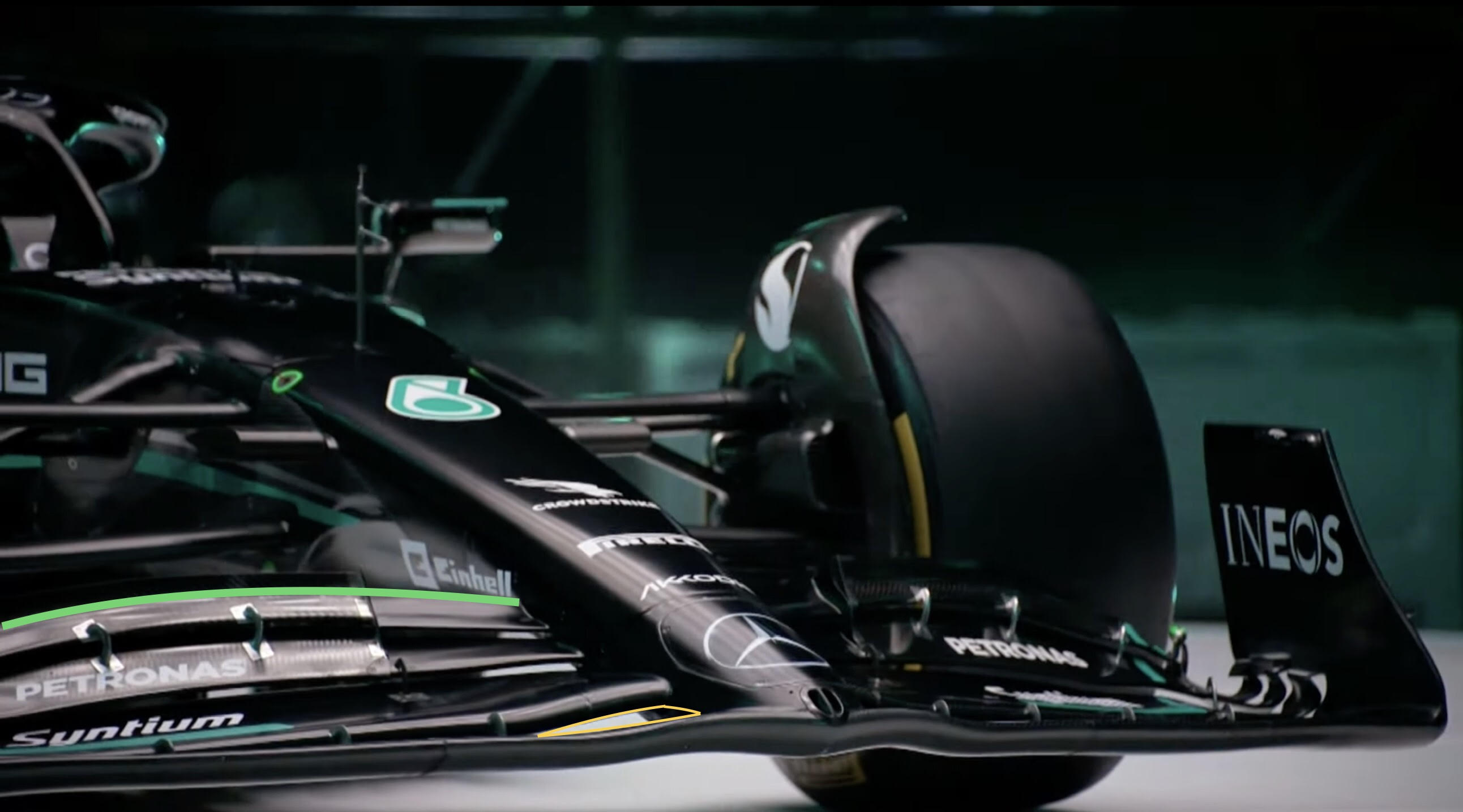
Last year, the second element’s inner end was partially hidden. This increased slot gap for this year will help the airflow stay attached to the inner end of the second, third and fourth elements, which should enable them to load that area of the front wing to a higher level. However, it won’t do a lot for the flow on the underside of the nose, which is probably the root cause of the flow separation on the inner part of the flaps.
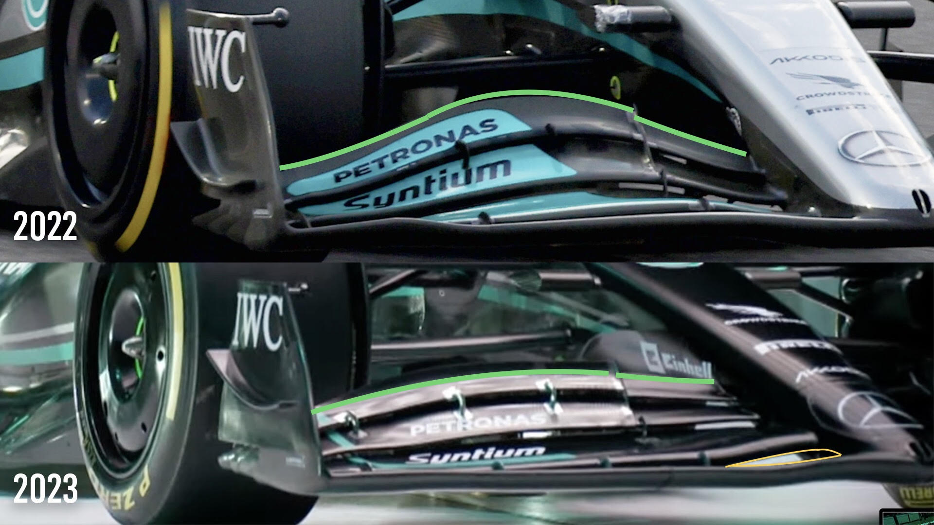
I have also highlighted the trailing edge of the fourth element of the front wing (green highlight). This will generate a much more uniform loading across the span, reducing transverse airflow that can be detrimental to the flow structure further downstream.
Last year, as you can see from the comparison, Mercedes was one of the only teams to run with this very highly loaded central section of the flap assembly. I questioned it on numerous occasions.
It is very difficult to see the detail of the front wishbone assembly. However, from what we can see it is similar to last year’s pushrod layout. It does look like the rear leg (red highlight) of the top wishbone is a little lower than last year. That leads me to think that it might be a multi-link front top wishbone assembly as opposed to a simple A-arm wishbone.
Using a multi-link top wishbone assembly gives you the opportunity to decrease the camber with steering lock, which will give you a larger tyre contact patch in slow corners.
The front track rod (magenta highlight) is in line with the forward leg of the lower wishbone (blue highlight). This is one way of getting around the 3.5:1 aspect ratio for the wishbone members.

By having the two in line, you end up with an aspect ratio of 7:1. If you can keep the two profiles aligned with each other when the steering lock is applied, it gives you more control over the wake coming off the trailing edge of the front wing rear element.
This brings us to the sidepod. The DNA remains the same, but with many detail changes. We also have to note that team principal Toto Wolff did say “the sidepods will change – not very soon, but we are looking at solutions”, so let’s see if Mercedes stays on this path or changes direction during the season.
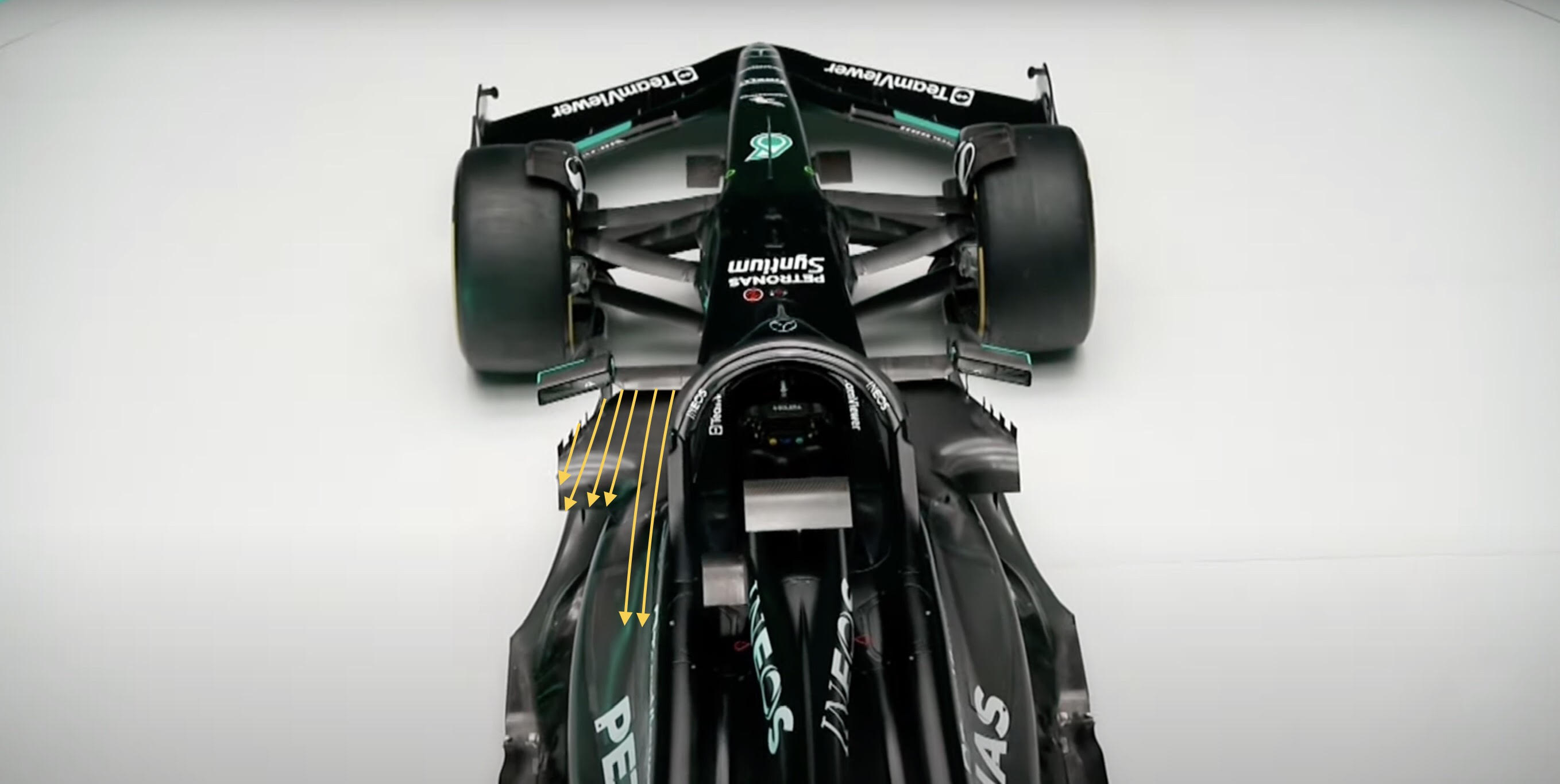
The solution to the location of the forward SIPs (side-impact protection) looks to be much more integrated into the top surface of the sidepod (yellow arrows). These components are supposed to be housed within the body surfaces, so this increased integration can help justify this concept.
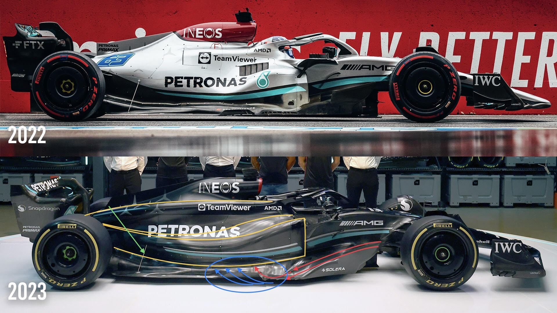
Relative to the other cars, the gap between the turbulent airflow behind the front tyre and the radiator intake is much larger. The gap to the leading edge of the underfloor is very similar and this large outer bargeboard, for want of a better word, is there to separate this turbulent flow allowing the underfloor to take a high percentage of its flow from nearer the centreline of the car.
I have put on some yellow flow lines where the surfaces intersect. As you can see, they are much more sympathetic to the flow than last year’s car. The upper line running off the rear end of the halo is also a cooling duct for whatever radiator system there is under the body surfaces. Some of the radiators will be mounted in the sidepods, some higher up.
As you can see the floor stay (green arrow) in front of the rear tyre is in a very similar position to last year’s. This shows that even with the outer edge of the floor being raised 15mm supporting the floor in this area is still critical to producing consistent underfloor downforce.
The extraction turning vanes on the edge of the floor (blue ellipse) are very similar to last year’s final version. The red flow lines coming over the top surface of the underbody leading edge will be travelling at a fairly high speed heading for the floor edge. When it trips on this outer deflector, some of it will be forced upwards scavenging flow (blue arrows) from the front corner of the underfloor.
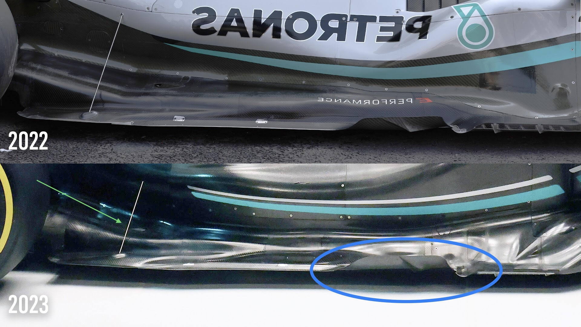
On this version of the floor, there is no attempt at doing anything to seal the rear section. This is all part of the change of aerodynamic regulations by the FIA when they lifted the outer edges up by 15mm to protect the teams from themselves and hopefully reduce the porpoising and in some cases bouncing.
I’m sure we will see some intricate details added but everyone will be keeping them as close to their chest as possible until testing starts next week.
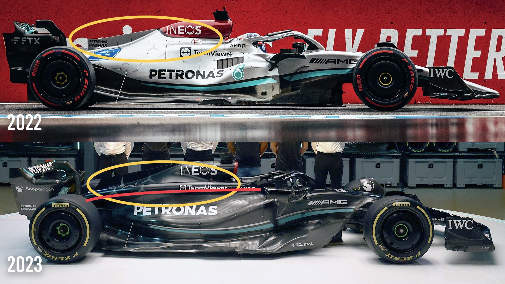
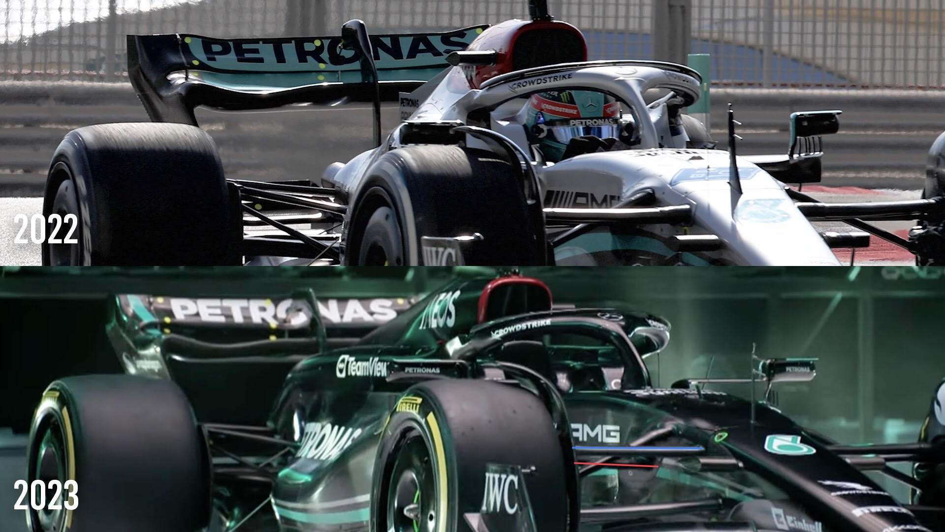
As shown by this comparison, the engine cover at the top of the engine (yellow ellipse) leaves more space for whatever is fitted inside there.
A clingfilm-wrapped internal component car is all well and good, but sometimes you ask a lot of the airflow to stay attached to quickly changing surfaces.
It also creates more cooling space under the body. The internal airflow on these cars is not quite as important as the external airflow, but you can’t just forget about it.
Having these two tunnels (red line) sweeping downwards to the exit area just beside the exhaust outlet will mean that the exhaust gas speed will have a positive influence on the radiator cooling. It also means that any turbulent flow from the exhaust outlet or the radiator outlet is all contained in one area, so makes it a bit easier to manage.
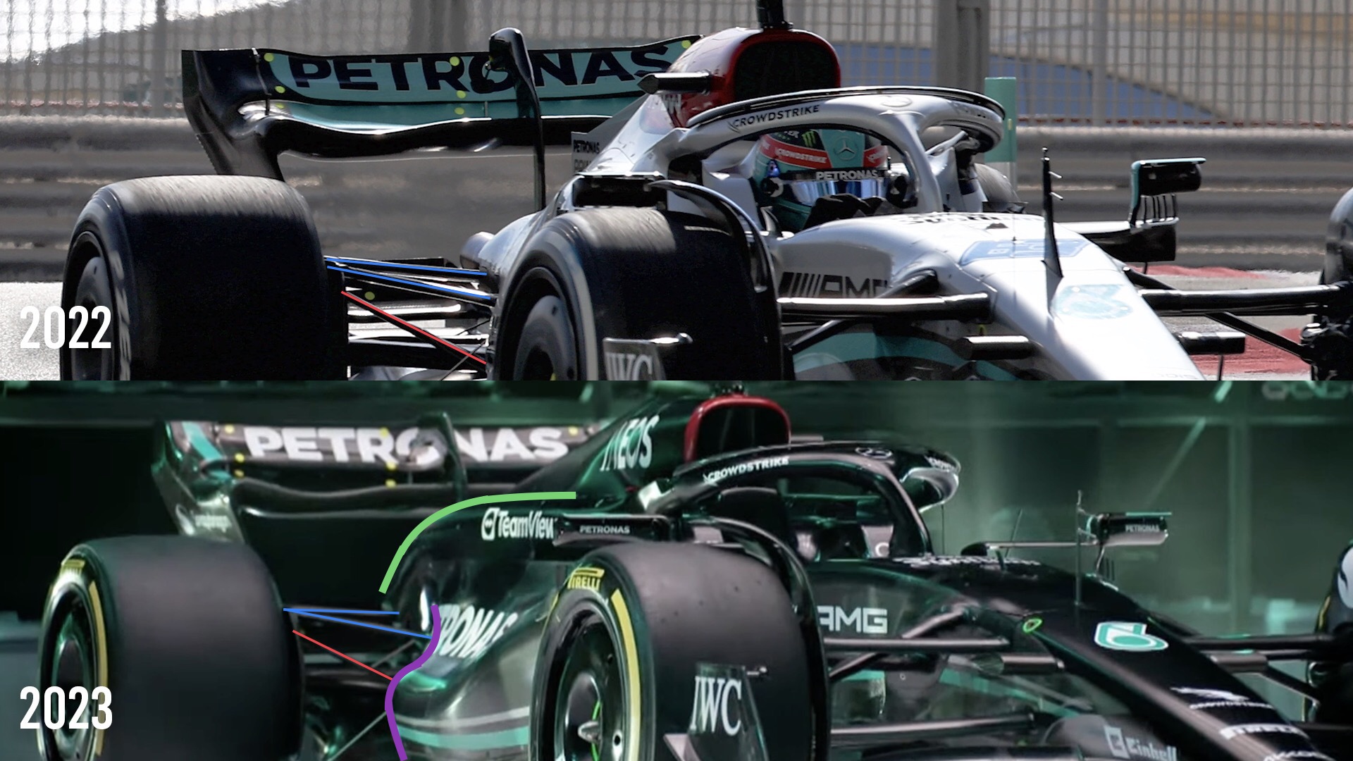
The rear suspension is difficult to see in detail. Although Mercedes has apparently made some modifications, it looks very similar to last year’s layout with a pullrod-operated inner rocker (red highlight).
The top wishbone (blue highlight) again very similar and has a small amount of anti-lift on it, as it did last year. The detail of the bottom wishbone is very difficult to see, but I won’t expect any major changes in that area.
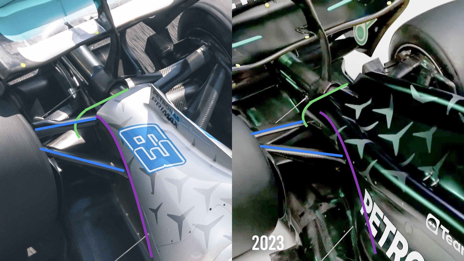
The more interesting details are the radiator exits and Coke bottle lines, which are more bulbous than last year’s car. The green and magenta lines are transposed as best possible using my etch-a-sketch from last year’s car to this year’s car. It shows roughly the reduction in the Coke bottle area.
However, the positive will be better underbody flow which will reduce the potential overheating problems that Mercedes suffered from on a few occasions last year. If cooling is an inherent problem with a car, the only quick fix is to turn down the heat source. In the case of a Formula 1 car, that is the power unit.
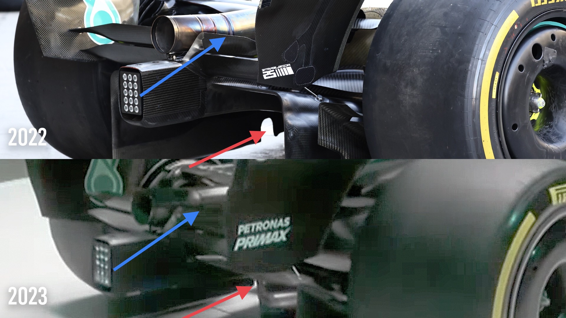
This rear-end shot doesn’t show too much. They are from different angles, but it looks like Mercedes still has the small cutout (red arrow) on the outer vertical side of the diffuser where the inner tyre squirt leaks through and helps to increase the speed of the airflow in that area.
The rear beam wing flap and trailing edge (blue arrow) again looks similar to last year. This is a very powerful component when it comes to the performance of the diffuser and the diffuser’s effect on the underfloor. All three have to work together to maximise the downforce load that the underfloor can generate.
CONCLUSION
The Mercedes W14 is a very neat and tidy car and it’s nice to see it in black even if it is only to save the weight of the paint. When we first ran the Jordan 191, or as it was called then the 911, it was all carbonfibre with no paint and it looked great.
On the surface, Mercedes has stuck to its concept. Yes, a few details changed here and there but as we all know it’s the parts we can’t see that will dictate the overall performance.
We might get a clue during pre-season testing, but we won’t really know for sure until qualifying for the first race of the season in Bahrain. That’s the time to hang it all out – and the stopwatch never lies.