
I’ve been saying for some time that I don’t understand why more Formula 1 teams don’t buy into the need for the slot gap between the tip of the nose and the forward element of the front wing.
Red Bull trialled both designs during the Bahrain test, which shows it’s important to make a comparison in the real world to understand which is the better option.
In the windtunnel, the difference between the two designs is probably minuscule because it’s impossible to run the car as low there as it does on the track. When you see the cars sparking, they are running in an unknown data condition so if you can’t research it and get accurate simulation data you need to add in a bit of ‘gut’ feel.
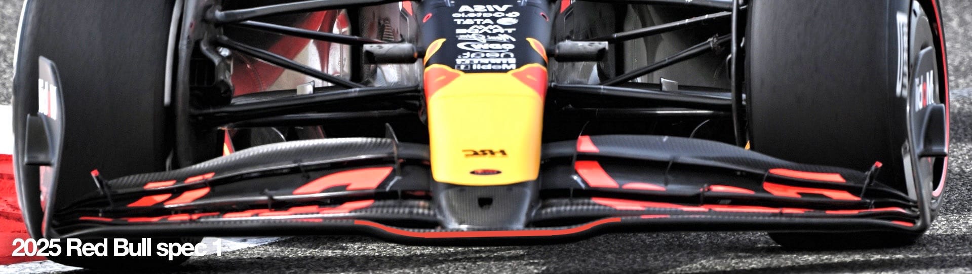
Looking at the nose-to-wing package Red Bull ran on its launch car (spec 1), I’m pretty sure the windtunnel data tells the team that the front wing gives a little more load from the central section (highlighted with the red line).
It is the furthest-forward part of the wing, meaning it has the most leverage over the front axle and, as it is also the lowest part, there are slightly more powerful ground effect characteristics from that part of the wing. The lower it gets to the ground, the faster the airflow has to travel through that diminishing gap to fill the void behind it – until, that is, it cries enough and you get what’s called airflow separation or airflow stalling.
Everything would point to this design producing more front load, especially when the car is that little bit higher in slow-to-medium speed corners. However, because it doesn’t have a slot gap, that part of the wing will stall when the car is too low to the ground because the airflow just doesn’t want to travel that fast.
The reduction of front load makes the car look less pitch sensitive. So from the data you are able to gather in the windtunnel you would say ‘you get more front load at low speed and less pitch sensitivity at high-speed and under braking, job’s a good ‘un’. But this is where that gut feel comes in.
You must remember that you are not running the car as low as it will be running on the circuit, so someone needs to ask the question: ‘what do you think will happen next when we venture into the unknown?’
When the underside airflow on that section of the wing stalls, the turbulent flow destroys the airflow to the central section of the underbody. This negatively affects the car’s main downforce-producing device: the floor.
As I have said many times, it is impossible to get data to feed the simulator with the car as close to the ground as it runs on the track. The simulator doesn’t have its own brain – for now at least - so they are only as good as the data you feed into them. If that data isn’t accurate, the answers you get will be rogue.
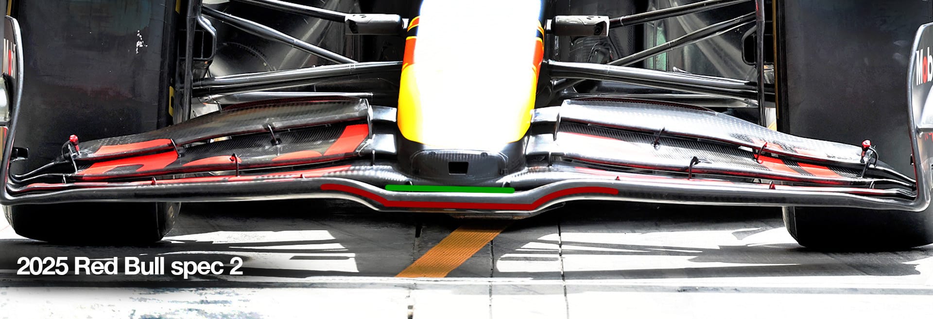
So now we come to the spec 2, with the slot gap. I have highlighted this with the green line.
It’s difficult to be exact, but the lowest section highlighted again with the red line looks a little shorter and the height change looks a little more abrupt. I’m not a fan of quick changes like this because it can introduce transverse airflow very quickly. The airflow under the centre section will be pulled outwards because the section just outboard of this transition is the hardest working part of the wing.
With this package, the central section of wing will not be as powerful because the slot gap will allow airflow to be pulled through the slot, meaning it’s not as powerful at low speed and medium speed. In the windtunnel, it will probably also be more pitch sensitive.
So all negative, I hear you say? Yes, but it will be more benign in real-world conditions, and that is why teams still struggle to decide.
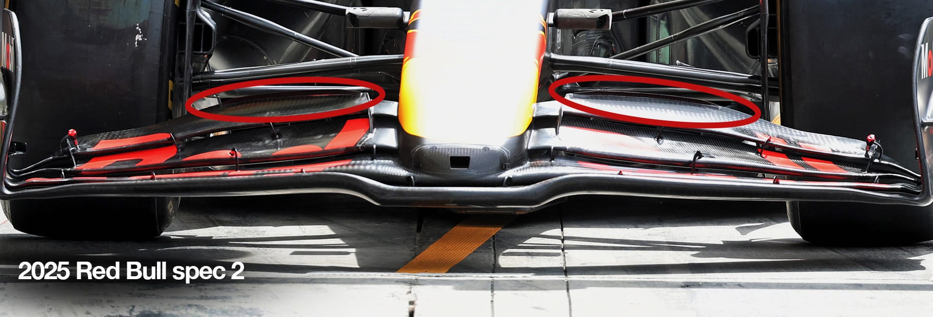
The low-speed reduction in downforce is being counteracted by fitting a small gurney flap, highlighted with the red ellipses. This is a small right-angle piece of carbon glued to the trailing edge of the rearmost wing flap, probably about 6mm in height. It acts as a trip on the trailing edge and is more effective at low airspeed than it is at high airspeed.
The positive for this package is that the underfloor will be seeing much more consistent airflow and the data you collect will be much more on point. Basically, the data won’t change anywhere near as much over those last few millimetres of ride height change, which are the few millimetres you can’t research. This means whatever you feed into the simulator will be a much more accurate reflection of what is actually happening on track.

