
Gary Anderson: The key design dilemma facing every F1 team
When coming up with a new package to suit current or, more importantly, new regulation concepts, the front and rear suspension layout is a major topic of discussion in the initial design meetings for every Formula 1 team.
The question of whether to go pushrod or pullrod and what the pros and cons of each system are is an important one. That’s because the configuration chosen can dramatically affect the overall structure and component positioning at both ends of the car.
It’s important to make the right decision early on as this is integral to the overall aerodynamic concept. You must take into account the fact the front suspension layout will influence both the aerodynamic concept, and more importantly the aerodynamic map that the underfloor produces as the ride height changes with speed and the car’s rake changes under braking and accelerating. This is exaggerated between a flat bottom car and a ground effect car.
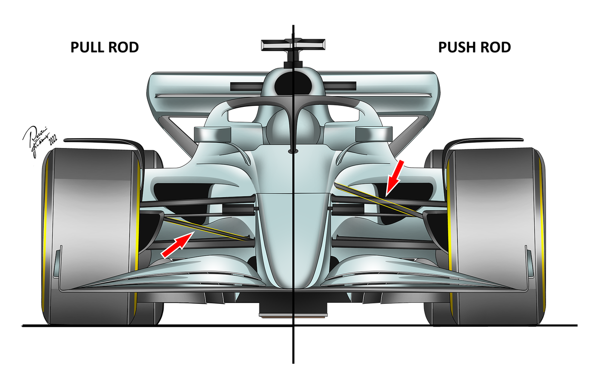
The push or pullrod is the suspension member connecting the wheel assembly to the inboard suspension system. With the pushrod, the inboard rocker assembly is mounted high on the chassis and the outboard end low on the wheel assembly. It’s called a pushrod because when the wheel reacts to a bump, it’s a push movement that via a rocker rotates the torsion bar on the inboard suspension.
With the pullrod, it’s the other way round: mounted low on the chassis but high on the wheel assembly with the actuation a pull movement.
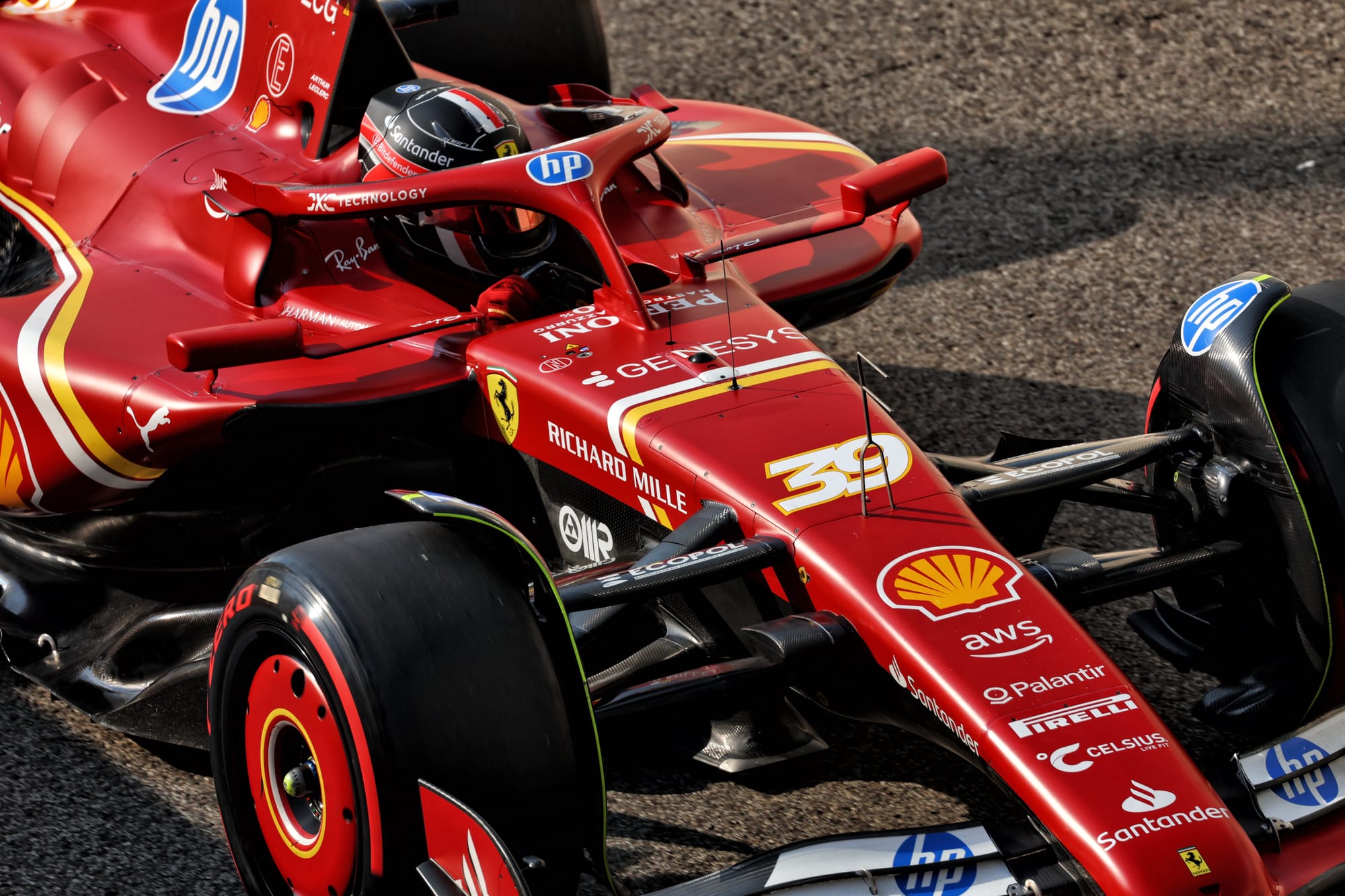
A little further down, I've selected early-2024 shots of the four leading cars in last year's constructors' championship and highlighted the relevant parts so you can see their pullrod versus pushrod suspension choices - showing it was a 50/50 split in choices.
I’ve also outlined the leading and trailing edge of the front wing in yellow. This is important because the suspension members aren’t just there to do their mechanical job of holding the wheels on, they also have an aerodynamic role by managing the airflow coming off the front wing to prepare it for the rest of the car downstream. You also want the minimum blockage to the airflow by the suspension, otherwise it will affect the performance of the front wing.
All wings have a leading edge and a trailing edge. The more open both these are the more efficient the wing will function; any blockage front or rear will simply affect its performance.
In each picture, the top front wishbone forward leg is green, the rearward leg is light green, the pullrod/pushrod is in red, the lower wishbone is in blue and the trackrod (if it’s separate rather than being in line or incorporated in the same aerodynamic shroud as another suspension member) is in light blue.
Ferrari had a pushrod system in 2024, but it also had a separate trackrod. This means there is just that little bit more blockage to the airflow, which in turn reduces the effectiveness of the front wing. Ferrari is expected to switch to a pullrod configuration in 2025.


This graphical comparison makes it easier to get into the pros and cons of the pushrod versus pullrod configurations.
Using the same colours to illustrate the components from car to car shows that there is very little difference in the area of the potential airflow blockage. On both systems, the double-ended orange arrow shows the angle between the pushrod and the wishbone component that drives it. The shallower the angle, the higher the loads in the triangular mechanism.
The final pick-up point location will define the loads, but in general they are as follows:
On the pushrod system, the lower wishbone’s forward leg main design requirements will be a compression load coming from the lateral corner force, and for the rear leg a compression load from the braking force. This layout creates a tension load from the vertical load. However, the pushrod is in compression, so needs to be a bigger cross section as it suffers from potential buckling.
On the pullrod system, the lower wishbone experiences more or less the same loads as the pushrod system, so there’s no big design difference there. The top wishbone forward leg is in compression, so may need to be slightly larger in section, but the main difference is the pullrod. This is in tension, so in theory a piece of wire would be adequate.
As an example, just look at a tug-of-war competition. The teams can exert incredible force on the rope in tension, but if they tried pushing the rope would just collapse.
As the pullrod is the component that crosses over the airflow coming off the front wing, the smaller the section the better.
In terms of the aerodynamic blockage created, it’s a 70/30 decision in favour of the pullrod.

Even though the front wing in this illustration is fairly basic, it does look like the pushrod (red line) would be more in line with the airflow coming off the trailing edge of the front wing, so I’m not seeing anything that would be massively aerodynamically beneficial in converting to a pullrod.
In terms of alignment to the front wing aerodynamically, it’s probably a 50/50 decision.
As for the mechanical layout, the structural requirements within the chassis for the mountings etc for either layout will basically be fairly similar.
This article first ran in The Race Members' Club on Patreon - join now for early access to columns from Gary, Mark Hughes, Edd Straw and more, plus exclusive bonus podcasts, ad free videos and podcasts, and chances to get your questions featured on our podcasts and in our articles
However, if you can take all that structural requirement and the inboard suspension components, which probably weigh in the region of 15kg, and move them down by 30cm-plus, you will effectively be lowering the centre of gravity by that much.
Lowering the overall centre of gravity is always a benefit, but there is also another centre of gravity benefit.
The overall centre of gravity ends up at one point on the chassis, but there is the centre of gravity axis. At the rear of the car, which has the main heavy components - the engine and gearbox - the centre of gravity is lower than it is at the front of the car.
This is because the centre of gravity of the chassis and the driver is higher, so the actual loads acting in the lateral suspension components, and in turn the tyre contact patch, will be higher on the front than on the rear. Unless this is catered for in the actual suspension geometry, which can dramatically affect the camber change due to vertical suspension movement, this can lead to a different jacking effect when that lateral force is applied. It will also be different from slow-speed to high-speed corners as the lateral force increases.
On these ground effect cars, which produce a high percentage of their downforce from the underfloor, different jacking front and rear can very easily compromise the balance and overall grip of the car between low- and high-speed corners.
Jacking is how much the ride height of the car changes when the cornering lateral forces are applied. If it is different front to rear, the aerodynamic centre of pressure of the underfloor will be moving around between corner entry and mid corner. Managing this and taking it into account on the overall aerodynamic map can be beneficial, but not managing this jacking can very quickly be confusing. On top of that, it’s not easy to research so a bit of ‘gut’ feel comes into play.
In terms of the structure and mechanical performance, it’s a 70/30 decision in favour of the pullrod.
With the pullrod layout, it is possible to get a much higher percentage of rising rate on the front suspension. Rising rate is when the car gets stiffer as the suspension compresses.
If you can double or triple the suspension rate as the car compresses towards the ground with the increase in aerodynamic load, then under braking the car will be much more stable. Also, between low and high speed it will allow you to run the car with a sensible vertical stiffness at slow speed to improve the front grip in low-speed corners and allow you to ride the kerbs, but also dramatically increase that vertical stiffness at high speed to give the stability the driver needs to commit to a 300km/h-plus (186mph+) corner and have the confidence that the rear end is not going to snap into oversteer.
When I say double or triple the suspension vertical rate, what I mean is that at low speed, say 100km/h (62mph), if you move the wheel vertically by one millimetre relative to the chassis you get ‘x’ twist on the torsion bar. At 200km/h, if you move the wheel vertically by one millimetre relative to the chassis, you get ‘2x’ degree twist on the torsion bar.
At 300km/h (186mph), if you move the wheel vertically by one millimetre relative to the chassis you get a ‘3x’ degree twist on the torsion bar.
These numbers are just a rough guide on what rising rate is. You need to look at it in conjunction with the increase in vertical aerodynamic load, which increases with the square of the speed - meaning twice the speed equals four times the vertical load.
In opportunity for greater rising rate, it’s a 70/30 decision in favour of the pullrod.
Going back in time, when the regulations allowed it and we had very high chassis for aerodynamic reasons, the pushrod system fitted in well. It allowed the lower part of the chassis to be as high as possible to allow the maximum airflow underneath it.

In 2013, for example, only Ferrari and McLaren had a pullrod system at the front. I never really understood this because if you had the chassis at its maximum height, the angle between top wishbone and the pullrod was minuscule - so it induced very high loads on the assembly, which in turn added weight.
Through the years, I have seen many different solutions, from coilover dampers where the pushrod currently goes, to a vertical inboard coilover damper driven by a top rocker. Even a floating vertical coilover damper driven by a top and bottom rocker, to vertical coil over dampers driven by pullrods and or pushrods, to the introduction of torsion springs and minute dampers.

This BRM P261, which Jackie Stewart won the 1965 Italian Grand Prix with, is a good example of what was used in the old days. It’s great to see this and the reality was just the same as the current design trend: some teams would get it right and some get it wrong.

This close-up of the front suspension shows in detail the rocker system that I am talking about, with the front rockers indicated by the red arrows. As I said earlier, this weight-wise versus stiffness was not the best solution and that is what led to the initial pullrod systems.

And this rear is the basic old-school system with a coil spring over a damper, highlighted by the arrows. You can easily see how much blockage this created but as with the current trend opening up the front gets priority - just.
The decision is never easy but in the end as far as the suspension configuration is concerned you need to make these decisions early to allow the design engineers to optimise whichever choice you have made.
For the front, I would be going for a pullrod system. As for the rear, that is something for another column...


